Hand force feedback and sensing system

Inactive Publication Date: 2006-11-21
RUTGERS UNIVERSITY
14 Cites 118 Cited by

AI-Extracted Technical Summary

Problems solved by technology

As such, it limited the ability to provide force feedback between any other fingers of the hand and also required...

Benefits of technology

[0010]The present invention relates to a force feedback and sensing system for a hand in which an actuator system and sensing system is coupled to a palm base attached to the hand or a glove. The actuator system includes double acting actuators which provide force feedback against dig...

Abstract

The present invention relates to a force feedback and sensing system for a hand in which an actuator system and sensing system is coupled to a palm base attached to the hand or a glove. The actuator system includes double acting actuators which provide force feedback against digits of the hand to simulate a real experience a user would have if directly manipulating a real object. The actuators are rotatably mounted to the palm base through a two degrees of freedom rotation joint.

Application Domain

Technology Topic

Image

  • Hand force feedback and sensing system
  • Hand force feedback and sensing system
  • Hand force feedback and sensing system

Examples

  • Experimental program(1)

Example

[0041]Reference will now be made in greater detail to a preferred embodiment of the invention, an example of which is illustrated in the accompanying drawings. Wherever possible, the same reference numerals will be used throughout the drawings and the description to refer to the same or like parts.
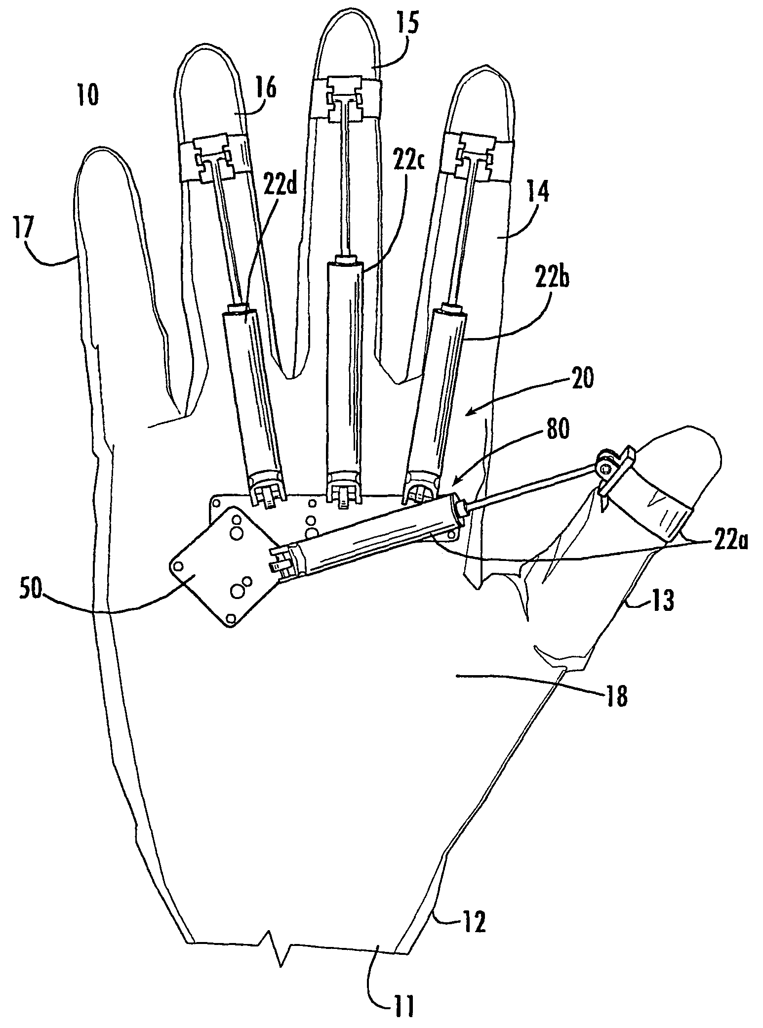
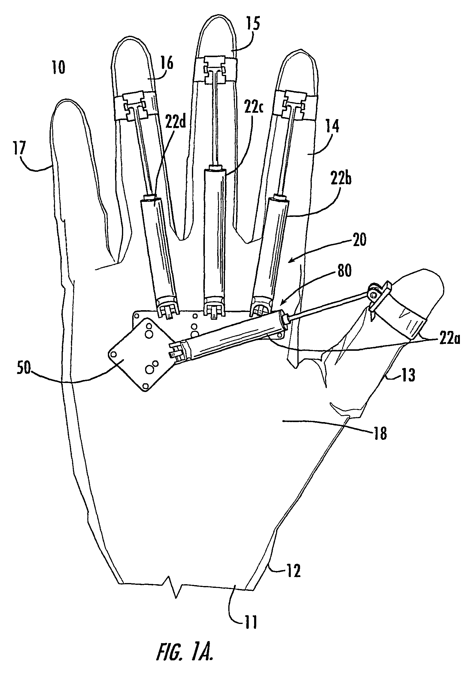
[0042]FIG. 1A is a front perspective view of hand force feedback and sensing system 10 in accordance with the teachings of the present invention. System 10 includes actuator system 20 and sensing system 80 coupled by palm base 50 to glove 12. Hand 11 is received in glove 12. Hand 11 has thumb digit 13, index finger digit 14, middle finger digit 15, ring finger digit 16 and little finger digit 17 each connected to palm portion 18. Preferably, actuator system 20, sensing system 80 and palm base 50 are lightweight. For example, system 10 can weigh less than about 100 g.
[0043]Actuator system 20 comprises actuators 22a, 22b, 22c and 22d which respectfully provide force feedback against thumb digit 13, index finger digit 14, middle finger digit 15 and ring finger digit 16. Accordingly, actuator 22a–22d aid in opening or closing of digits 13–16. The force feedback is simulative of the real experience a user would have if directly manipulating a real object. It has been found that four actuators are sufficient to provide realistic response. It will be appreciated that actuator system 20 can be expanded to also include an actuator for providing force feedback against little finger digit 17. Glove 12, hand 11 and system 10 can have different sizes, i.e. “small”, “medium” and “large”.
[0044]In an alternate embodiment shown in FIGS. 1B–1D, palm base 50 is attached directly to hand 11 with hand mount 300. FIG. 1B illustrates actuator 22b attached to palm base 50. It will be appreciated that actuators 22a, 22c and 22d can be also attached to palm base 50. Hand mount base 302 is attached with a plurality of side mounts 304 to palm base 50. For example, side mounts 304 can be formed of flexible beams. End 305 of side mounts 304 include aperture 306. Aperture 306 is received over post 308 attached to palm base 50. End 309 of side mounts 304 is received in self-locking head 310. During use, hand 11 is received between bottom surface 311 of palm base 50 and top surface 312 of hand mount base 302 and hand 11 is coupled by side mounts 304 to palm base 50. Hand mount base 302 includes apertures 312 as shown in FIGS. 1B and 1C. Attachments 313 to wrist position sensor 314 is received in apertures 312. Wrist position sensor 314 can be a six degree of freedom position sensor, for example as manufactured by Polhemus Inc. as “Fast Track”.
[0045]Each of actuators 22a–22d comprise moveable piston 23 which moves within cylinder body 24, as shown in FIG. 2A. In a preferred embodiment, cylinder body 24 is formed of outer cylinder 25 and inner cylinder 26 which are seated on bottom cylinder cap 27. Outer cylinder 25 is preferably formed of a metal, such as stainless steel, for supporting radial force or torques on cylinder body 24. Preferably, inner cylinder 26 is formed of resistive glass, such as Pyrex, for supporting air pressure.
[0046]Gasket 28a seals inner cylinder 26 to outer cylinder 25 and bottom cylinder cap 27. Gasket 28b seals top portion 36 of inner cylinder 26 to outer cylinder 25. Aperture 29a is formed through gasket 28a and aperture 29b is formed in gasket 28b. Air inlet 30 is positioned through bottom portion 32 of outer cylinder 25, as shown in FIG. 2B. Air inlet 31 is positioned through bottom cylinder cap 27. Air 33 from air inlet 30 received through aperture 29a in gasket 28a circulates upwardly in the direction of arrow A1, between outside 34 of inner cylinder 26 and inside 35 of outer cylinder 25 through aperture 29b in gasket 28b to top portion 36 of inner cylinder 26. Air 33 enters from top portion 36 of inner cylinder 26 and pushes downwardly in the direction of arrow A2 thereby compressing piston 23 within inner cylinder 26. Air 37 from air inlet 31 circulates upwardly in the direction of arrow A3 thereby extending piston 23 within inner cylinder 26. Accordingly, cylinder body 24 is a double acting cylinder providing both compression and extension of piston 23. Air 33 and air 37 are pressurized, for example air 33 and air 37 can be pressurized up to about 100 psi, and air 33 and 37 is clear of oil and water.
[0047]Piston rod 38 extends from piston 23 of cylinder body 24 as shown in FIG. 3A. The size of actuator 22a–22d in the extended position of piston rod 38 is inversely proportional to the minimum size of a virtual object that can be grasped by a user of system 10. The size of actuator 22a–22d can be defined by the compression rate which corresponds to the rate of closing of a respective digit 13–16.
[0048]Preferably, for the “large” size, cylinder body 24a has a length of about 1.65 inches in compressed position and a length of about 3.0 inches in the extended position, cylinder body 24b has a length of about 1.75 inches in compressed position and a length of about 3.25 inches in the extended position, cylinder body 24c has a length of about 2.0 inches in compressed position and a length of about 3.75 inches in the extended position, cylinder body 24d has a length of about 1.90 inches in compressed position and a length of about 3.50 inches in the extended position. The size of actuator 22a–22d for “medium” size and “small” size are respectively 10% and 20% less than the size for the “large” size. Accordingly, cylinder body 24 has a compression rate of 54%, 58% and 62% for the “large”, “medium” and “small” sizes respectively.
[0049]Piston rod 38 is fixed within piston 23, as shown in FIG. 3B. Piston 23 is received within inner cylinder 26. Preferably, piston 23 is formed of material having a low coefficient of friction. For example, piston 23 can be formed of a carbon and graphite material. Preferably, piston rod 38 is coupled to piston 23 with spherical joint 40 and silicon joint 41, for reducing the constraint caused by any error of alignment between piston rod 38 and inner cylinder 26, thereby reducing air leaks between piston 23 and inner cylinder 26.
[0050]FIGS. 4A and 4D illustrate attachment of actuator 22a–22d to palm base 50. Joint 42 rotatably attaches bottom cylinder cap 27 to palm base 50 for allowing two degrees of freedom rotation. Joint 42 provides rotation on a flexion axis, axis AF, thereby providing front to back rotation of respective digits 13–17 in the direction of arrow A5 in about a 120° angular range, as shown in FIG. 4B. Joint 42 provides rotation on an abduction/adduction axis, axis AA, thereby providing side to side rotation of respective digits 13–17 in the direction of arrow A4 in about a 60° angular range.
[0051]Bearings 43 rotatably mount side surface 46 of leg 44 of bottom cylinder cap 27 to palm base 50 for providing rotation on flexion axis AF. Bearings 45 rotatably mount bottom surface 48 of leg 44 of bottom cylinder cap 27 to palm base 50 for providing rotation on abduction/adduction axis, AA. Preferably bearings 43 and 45 are miniature, for example, bearings 43 and 45 can have an inner diameter of about 0.04 inches and an outer diameter of about 0.125 inches for reducing friction. Flexion axis, AF, abduction axis, AA, and cylinder axis, AC, intersect at a single point, P, for providing improved error during computation of a kinematics model of each finger for a sensor located at point P, as described below.
[0052]FIGS. 5A–5C illustrate palm base 50. Tubing 52 connects to air inlet 30 of each of actuators 22a–22d. Preferably, tubing 52 is mounted or integrally connected to palm base 50 for allowing full range of motion of actuator 22a–22d. Tubing 52 is preferably formed of a flexible material. A suitable material for tubing 52 is silicon, rubber or polyvinylchloride (PVC). A fabric material can be used to surround tubing 52. Bottom surface 53 of palm base 50 has a rounded shape as shown in FIG. 5C. Preferably, the outer diameter of bottom surface 53 is in the range of about 10 mm to about 20 mm and most preferably is about 13 mm. It will be appreciated that additional tubing not shown can be connected to air inlet 31 and integrated inside palm base 50.
[0053]Palm base 50 is attached approximately at middle portion 54 of palm 55 adjacent the metacarpal phalanx crease line, as shown in FIGS. 6A–6B. The shape and size of bottom surface 53 of palm base 50 provides complete flexion of the metacarpal phalanx and is more comfortable in a user's hand than a flat shape. Digit 13 includes bottom joint 56 and fingertip joint 58. Digits 14–17 each include bottom joint 56, middle joint 57 and fingertip joint 58. In the compressed position shown in FIG. 6A, piston rod 38 is compressed within cylinder body 24 for closing bottom joint 56, middle 57 and fingertip joint 58, thereby providing force feedback for simulating grasping of an object. In the extended position shown in FIG. 6B, piston rod 38 is extended from cylinder body 24 for extending bottom joint 56, middle 57 and fingertip joint 58.
[0054]Fingertip joint 58 of each of digits 13–17 is attached to a piston rod 38 of a respective actuator 22a–d with fingertip mount 60, as shown in FIGS. 7A and 7B. Fingertip mount base 61 of fingertip mount 60 is attached adjacent to bottom surface 59 of fingertip joint 58. A plurality of side mounts 62 are attached to fingertip mount base 61. Side mounts 62 have a rounded shape for sliding over fingertip joint 58. For example, side mounts 62 can be formed of flexible beams. A suitable material for side mounts 62 is stainless steel covered with silicon rubber. Screws 65 mount side mounts 62 to fingertip mount base 61. Side mounts 62 are received in self-locking head 66 for coupling fingertip mount 60 to fingertip joint 58. Release latch 67 releases side mounts 62 from self-locking head 66 for removal of fingertip mount 60 from fingertip joint 58.
[0055]Legs 68a and 68b extend from bottom surface 69 of fingertip mount base 61. Axle 70 connects upper portion 71 of piston rod 38 to legs 68a and 68b. Ends 72a and 72b of axle 70 are rotatably mounted to respective legs 68a and 68b with bearings 74 for providing one degree of freedom rotation. Bearings 74 can be similar to bearings 43 and 45 described above.
[0056]FIGS. 8–11 illustrate sensing system 80. Sensing system 80 comprises linear sensor 81, abduction angular sensor 100, flexion angular sensor 102 and force sensor 110 which are each coupled to palm base 50 for example with a PCB sensor board. Linear sensor 81 includes reflective infrared sensors 82a, 82b and 82c which are mounted to palm base 50 and coupled to a respective actuator 22a–22d, as shown in FIG. 8A. Reflective infrared sensor 82a, 82b and 82c measure the linear position of digits 13–17.
[0057]Fiber optic cables 83a, 83b and 83c connect respective reflective infrared sensors 82a, 82b and 82c to bottom cylinder cap 27. Fiber optic cables 83a, 83b and 83c extend through respective apertures 84a, 84b and 84c in bottom cylinder cap 27. Infrared waves 85 generated from reflective infrared sensor 82a travel through fiber optic cable 83a and are emitted by infrared emitter 86 coupled to fiber optic cable 83a. Infrared waves 85 are reflected by mirror 87 as reflected infrared waves 88. Mirror 87 is attached to bottom surface 99 of piston 23. Mirror 87 is thin, preferably having a thickness of about 0.02 inches to about 0.04 inches. Infrared waves 85 can also be reflected off mirror 27 towards inner cylinder 26 and reflected off inner cylinder 26. Reflected infrared waves 88 are received at infrared receptors 89a, 89b coupled to fiber optic cables 83b, 83c. Reflected infrared waves 88 travel through fiber optic cables 83b and 83c to reflective infrared sensors 82b, 82c. Reflective infrared sensors 82b, 82c use the values of reflected infrared waves 88 to determine the position of piston 23. It will be appreciated that additional infrared emitters and infrared receptors can be used in accordance with the teachings of the present invention to increase accuracy of the linear position measurement.
[0058]Preferably, reflective material 90 combined with absorbing material 91 form cover 95 of outside portion 34 of inner cylinder 26 to allow inner cylinder 26 to reflect infrared waves. Surface 92 of reflective material 90 increases progressively from bottom portion 32 to top portion 36 of inner cylinder 26. Surface 93 of absorbing material 91 decreases from bottom portion 32 to top portion 36 of inner cylinder 26. The combination of progressively increasing absorptive material and progressively decreasing absorptive material reduces sudden intensity variations between extreme positions at bottom portion 32 and top portion 36 of inner cylinder 26 for allowing accurate calibration of reflective infrared sensors 82a, 82b and 82c.
[0059]Abduction angular sensor 100 measures the abduction angle, angle AA for measuring abduction motion, as shown in FIG. 9A. Abduction angle sensor 100 is mounted to palm base 50. Flexion angle sensor 102 measures angle flexion, angle AF, for measuring flexion motion, as shown in FIG. 9B. Flexion angle sensor 102 is mounted to bottom surface 105 of bottom cylinder cap 27. A pair of polarized magnet discs 108, 109 are mounted at 90° to one another to provide a magnetic field having a magnetic field of constant variation for abduction angle sensor 100 and flexion angle sensor 102, as shown in FIG. 9C. Legs 106 extend from bottom cylinder cap 27. Magnetic disc 108 is coupled by axle 104 to legs 106 of bottom cylinder cap 27 with bearings 107. The axis of magnet disc 108 and the axis of magnet disc 109 intersect at one point P2. Each point around P2 has a determined intensity of the magnetic field which is independent of motion of cylinder body 24. Abduction angle sensor 100 and flexion angle sensor 102 measure the magnetic field of magnetic discs 108 and 109. For example, abduction angle sensor 100 and flexion angle sensor 102 can be Hall effect sensors which sense magnetic fields. Abduction angle sensor 100 measures abduction rotation of about 60 degrees from about −30 degrees to about 30 degrees. Flexion angle sensor 102 measures flexion rotation of about 120 degrees from about 10 degrees to about 110 degrees.
[0060]Force sensor 110 measures forces applied by fingertip joint 58, as shown in FIG. 10. Force sensor 110 comprises strain gauge 112 positioned on portion 114 of palm base 50 adjacent to respective rotatably mounted actuators 22a–22d. Fingertip forces in the direction of arrows F1 and F2 are measured based on the torque value represented by torque T, measured by strain gauge 112, angle θ and distance D.
[0061]FIG. 11 is a schematic diagram of actuator interface 200. Position signals 201 from sensing system 80 are received at analog demultiplexer 202. Position signals 201 from sensing system 80 can include signals from linear sensor 81, abduction angle sensor 100, flexion angle sensor 102 and force sensor 110 respectively received from actuator 22a–22d of a small hand, a medium hand or a large hand. Analog demultiplexer 202 decouples position signals 201 from sensing system 80. Output signals 203 from analog demultiplexer 202 are converted by analog to digital converter 204 to digital position signals 205. Digital position signals 205 are received at on-board computer 206 and forwarded to host computer 207. Digital signals 205 can be forwarded, for example, over an RS232 connection to host computer 207. For example, on-board computer 206 can be an embedded Pentium PC.
[0062]Host computer 207 determines force feedback to be applied to actuators 22a–22d. Force feedback signals 208 generated by host computer 207 are forwarded to on-board computer 206. On-board computer 206 passes valve control signals 209 to digital to analog converter 210. Analog valve control signals 211 are received at valve controller 212. Valve controller 212 controls intake valves 213 and exhaust valves 215 to determine a pressure for pressurized air 216. Air pressure is provided by air compressor 217. Pressurized air 215 is sensed by pressure sensors 218. Pressure output 219 from pressure sensor 218 is converted with analog to digital converter 220 and is received at on-board computer 206. Multiplexer pneumatic valves 222 interface actuators 22a–22d for providing pressurized air 215. Multiplexer pneumatic valves 222 are controlled by on-board computer 206 through I/O port 224. Actuator interface 200 is similar to the interface described in U.S. Pat. No. 5,354,162 hereby incorporated by reference into this application.
[0063]Monitor 225 can display a virtual environment simulation, interacting with host computer 207. If complexity of on-board computer 206 is increased host computer 207 can be omitted.
[0064]Kinematic transformations are used to transform the desired position of actuators 22a–22d into a position of piston 23 for extending piston rod 38 from outer cylinder 25, as shown in FIGS. 6A and 6B. For example, conventional techniques for inverse kinematic transformations to output the lengths of cylinders or pistons necessary to reach a desired position, such as described in J. E. Dieudone, R. V. Parrish, & R. E. Bardusch, An Actuators Extension Transformation for a Motion Simulator and an Inverse Transformation Applying Newton-Raphson's Method, NASA, 1972 hereby incorporated by reference into this application and for forward kinematics transformations such as described in C. C. Nguyen & F. J. Pooran, Kinematic Analysis and Workspace Determination of a 6 DOF CKCM Robot End-Effector, Journal of mechanical Working Technology, 1989, 00. 283–294, hereby incorporated by reference into this application, can be implemented by host computer 207.
[0065]It is to be understood that the above-described embodiments are illustrative of only a few of the many possible specific embodiments which can represent applications of the principles of the invention. Numerous and varied other arrangements can be readily devised in accordance with these principles by those skilled in the art without departing from the spirit and scope of the invention.

PUM

no PUM

Description & Claims & Application Information

We can also present the details of the Description, Claims and Application information to help users get a comprehensive understanding of the technical details of the patent, such as background art, summary of invention, brief description of drawings, description of embodiments, and other original content. On the other hand, users can also determine the specific scope of protection of the technology through the list of claims; as well as understand the changes in the life cycle of the technology with the presentation of the patent timeline. Login to view more.

Similar technology patents

Air-floated high-speed motorized spindle

InactiveCN102489726AEliminate mechanical frictionReduce frictionMachine tool componentsLarge fixed membersStatorEngineering
Owner:GUANGZHOU HAOZHI ELECTROMECHANICAL

Classification and recommendation of technical efficacy words

Why Eureka
Try Eureka