
Polarizing turning film using total internal reflection

a technology of internal reflection and polarizing film, applied in the field of turning film, can solve the problems of reducing the overall contrast reducing the efficiency of the illumination system, so as to achieve the effect of improving the overall contrast, improving the illumination system design, and increasing the cost of the illumination system design

Active Publication Date: 2006-11-21
SK MICROWORKS SOLUTIONS CO LTD
View PDF8 Cites 55 Cited by
  • Summary
  • Abstract
  • Description
  • Claims
  • Application Information

AI Technical Summary

Benefits of technology

[0014]It is an advantage of the present invention that it provides a single component that combines turning film and polarizer functions for illumination that is incident over a range of principal angles.

Problems solved by technology

However, overall contrast, even with a BEF, remains relatively poor.
While this approach has merit for providing some measure of polarization, however, there are practical limits to how much improvement can be gained based on simply specifying an index of refraction n. Moreover, embodiments utilizing multiple turning films add cost, thickness, and complexity to the illumination system design.
While this method has the advantage of incorporating polarization components within the light guide itself, there are disadvantages to this type of approach.
Thus, it can be seen that, while there have been attempts to provide polarized illumination by incorporating the polarization function with other components, these attempts have not provided flexible, less costly, and more effective solutions.

Method used


Image

  • Polarizing turning film using total internal reflection
  • Polarizing turning film using total internal reflection
  • Polarizing turning film using total internal reflection

Examples


example 1

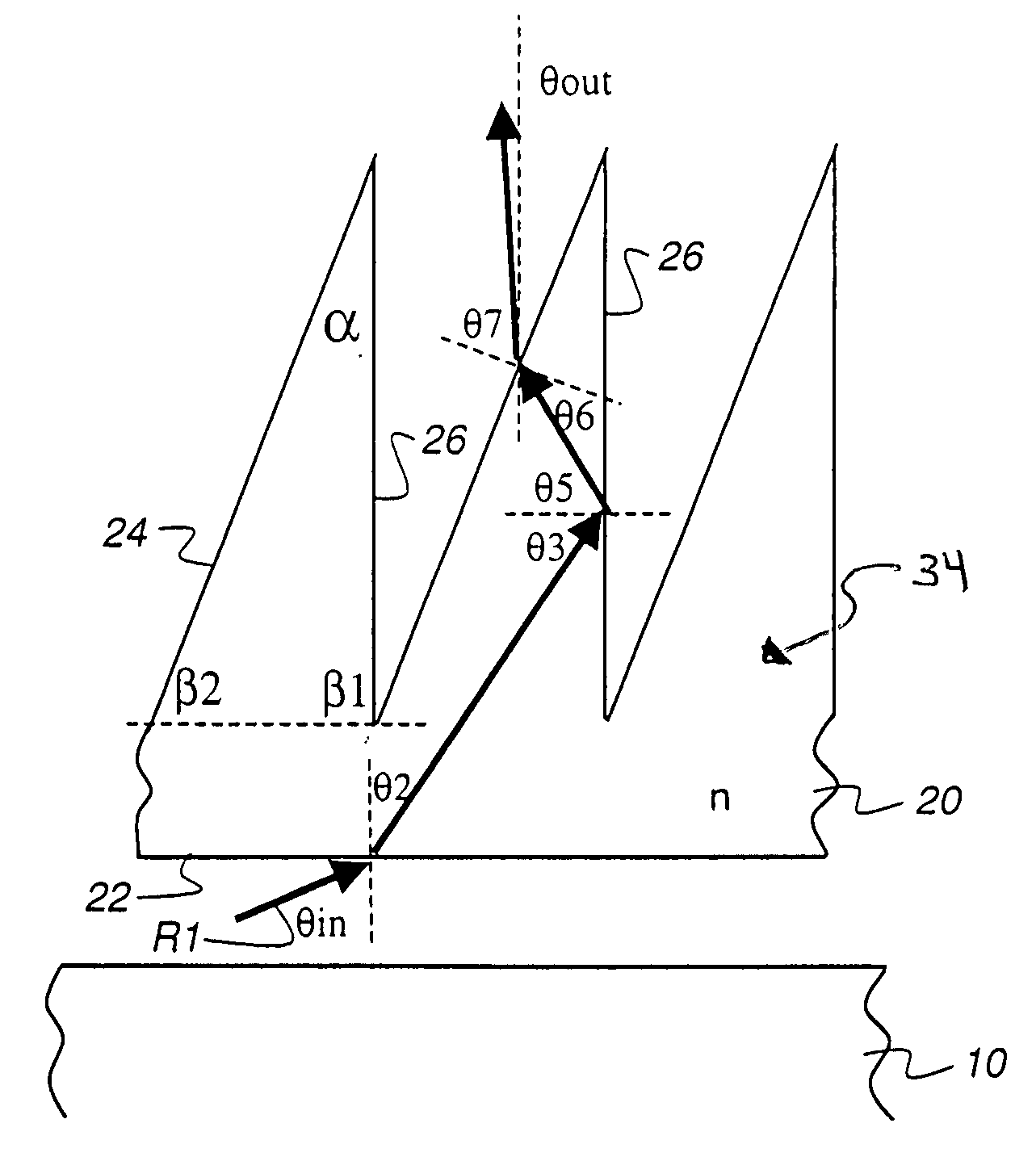
[0071]Referring to the contour plots of FIGS. 8A-8D, the input angle θin=63°. In these plots, the abscissa (x-axis) shows the far base angle; the ordinate (y-axis) shows index of refraction n. FIGS. 8A through 8D are organized in a sequence that can be described with respect to FIG. 3A. FIG. 8A shows response at the first interface, at which light from light guiding plate 10 is incident on flat surface 22. FIG. 8B shows response at the second interface, where light within turning film 20 is incident on far surface 26. FIG. 8C shows output angle response, θout. FIG. 8D is a composite contour plot, showing the overlap of results by the combined conditions represented in FIGS. 8A, 8B, and 8C. The composite contour plot of FIG. 8D then shows the “working space” available for the design of turning film 20 providing optimized polarization separation.

[0072]FIG. 8A is a contour plot with areas 1 and 2 showing a parameter space of far base angle β1 and index of refraction satisfying |θin−θb|...

example 2

[0078]FIGS. 9A through 9D show a similar sequence to that of FIGS. 8A through 8D, using the same light redirecting structures and materials, but with an input principal angle θin=70°. By comparison with FIG. 8A, note that area 1 |θin−θb|2 |θin−θb|3 |θin−θb|1 |θout|in−θb|4−θb|3, where |θout|in−θb|4−θb|4 satisfying |θout|in−θb|4−θb|<10°.

example 3

[0079]FIGS. 10A through 10D show a similar sequence to that of FIGS. 9A through 9D, using the same structures and materials, but with an input principal angle θin=75°. Neither Area 1 |θin−θb|2 |θin−θb|3 in FIG. 10A satisfies |θin−θb|3 satisfies |θout|in−θb|4−θb|4 satisfies |θout|in−θb|4−θb|<10°.

[0080]As one advantage of the present invention, polarizing turning film 20 can be formed as a light redirecting article that can be adapted to accept light over more than one principal angle or range of principal angles. Referring again to FIG. 3A, a first range of principal angles would be used to determine the relative slant of far surface 26 when turning film 20 is disposed in one position. Turning film 20 can alternatively be used in an orientation in which it is rotated, within the same plane, 180 degrees from its original position. As shown in FIGS. 20A and 20B, turning film 20 is disposed in one position when incident light is at principal angle θin1 and is rotated 180 degrees within ...


PUM


Abstract

A light redirecting article redirects light toward a target angle. The light redirecting article has an input surface for accepting incident illumination over a range of incident angles and an output surface with a plurality of light redirecting structures, each light redirecting structure having an internal reflection surface oriented at a first angle with respect to the plane of the input surface and an exit surface for emitting an output light at an emitted light angle, wherein the exit surface is oriented at a second angle relative the plane of the input surface. For incident illumination at a principal angle greater than 60 degrees from normal, light is reflected from the internal reflection surface and emitted from the exit surface at an emitted light angle that is within 5 degrees of the target angle.

Description

FIELD OF THE INVENTION[0001]This invention generally relates to display illumination articles for enhancing luminance from a surface and more particularly relates to a turning film that redirects light from a light guiding plate and provides polarized light output.BACKGROUND OF THE INVENTION[0002]Liquid crystal displays (LCDs) continue to improve in cost and performance, becoming a preferred display type for many computer, instrumentation, and entertainment applications. The transmissive LCD used in conventional laptop computer displays is a type of backlit display, having a light providing surface positioned behind the LCD for directing light outwards, towards the LCD. The challenge of providing a suitable backlight apparatus having brightness that is sufficiently uniform while remaining compact and low cost has been addressed following one of two basic approaches. In the first approach, a light-providing surface is used to provide a highly scattered, essentially Lambertian light d...

Claims


Application Information

Patent Timeline
IPC IPC(8): G02B5/30
CPCG02B6/0053G02B6/0056G02B5/30G02B6/00G02F1/1335
Inventor MI, XIANG-DONG
Owner SK MICROWORKS SOLUTIONS CO LTD
Learn More