Diffractive optical element

a technology of diffractive optical elements and optical elements, which is applied in the direction of microlithography exposure apparatus, photomechanical treatment, instruments, etc., can solve the problems of high degree of detail of mechanical methods, high cost and error-prone, and the limitation of very short wavelengths of light, etc., and achieve high resolution

Inactive Publication Date: 2006-11-21
CARL ZEISS SMT GMBH
View PDF8 Cites 12 Cited by
  • Summary
  • Abstract
  • Description
  • Claims
  • Application Information

AI Technical Summary

Benefits of technology

[0010]It is an object of the present invention to provide a blazed diffractive optical element of the type mentioned in the introduction, which can be produced with a high resolution in one process cycle.
[0012]According to the invention, individual substructures with comparatively large closed surfaces are used, and these are exclusively structured laterally. This makes it possible to work about one order of magnitude lower than the aforementioned process technology limits in the prior art. Furthermore, the diffractive optical elements according to the invention can be produced much more quickly and therefore less expensively.
[0019]The production of a polygonal or curved side surface of the diffraction structures with the aid of the known microlithographic methods can be facilitated if it is approximated by a step curve which, for example, corresponds to the increment of the lithographic scriber.
[0021]Besides a region with the aforementioned binary blazed diffraction structures, the optical element may also have another region which contains conventionally blazed diffraction structures having an at least approximately ramped profile. Such a combination of binary and conventionally blazed diffraction structures in an optical element is preferable, in particular, when the different diffraction efficiencies of the binary and conventionally blazed diffraction structures are intended to be utilised. Whereas a controlled local modification of the diffraction efficiency in the case of purely conventionally blazed diffraction structures is only possible by detuning, i.e. by reducing the inherently possible diffraction efficiency, a local increase in the diffraction efficiency can also be achieved by the use of binary blazed diffraction structures. The diffraction efficiency, integrated over the entire surface of the optical element, can thereby be increased compared with elements having purely conventionally blazed diffraction structures.
[0035]In a preferred exemplary embodiment of the invention, the maximum dimensions p in the longitudinal direction of at least two individual substructures within a diffraction structure are unequal. This is because it has been found that the diffraction effect of the optical element can actually be improved by this breaking of the strict periodicity, since it avoids so-called stitching or alignment defects which may occur in strictly periodic arrangements of very small structures and can lead to undesirable scattered light.

Problems solved by technology

This mechanical method is highly elaborate, on the one hand, and on the other hand it encounters limitations with very short wavelengths of the light for which the grating is intended to be used, since the structures to be produced are too small.
The production of such a grating, however, is cost-intensive and error-prone because it is necessary to carry out the process cycle repeatedly.
They are therefore technologically highly elaborate and expensive to produce, and cannot be made with sufficient accuracy.

Method used


Image

  • Diffractive optical element
  • Diffractive optical element
  • Diffractive optical element

Examples


Embodiment Construction

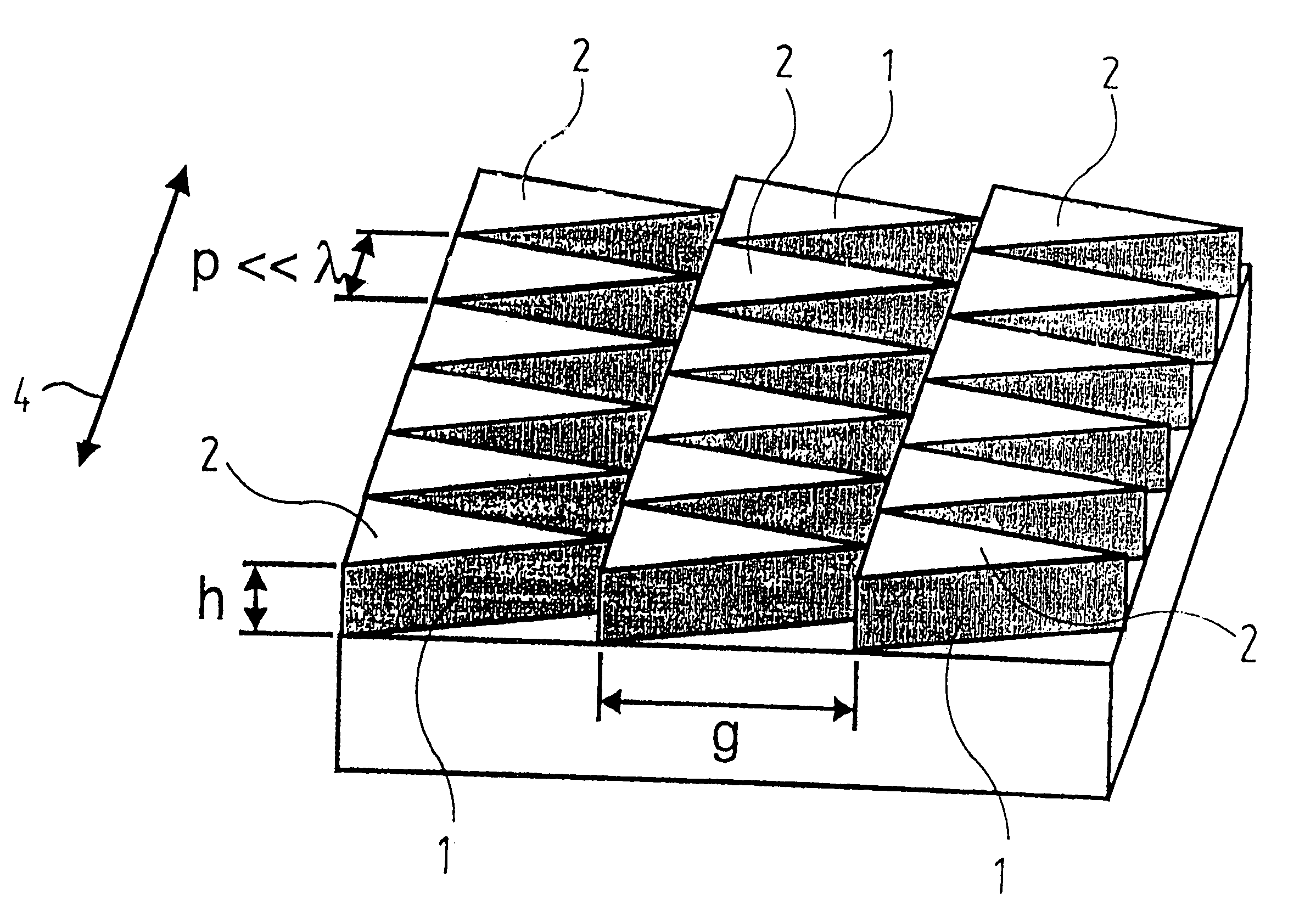
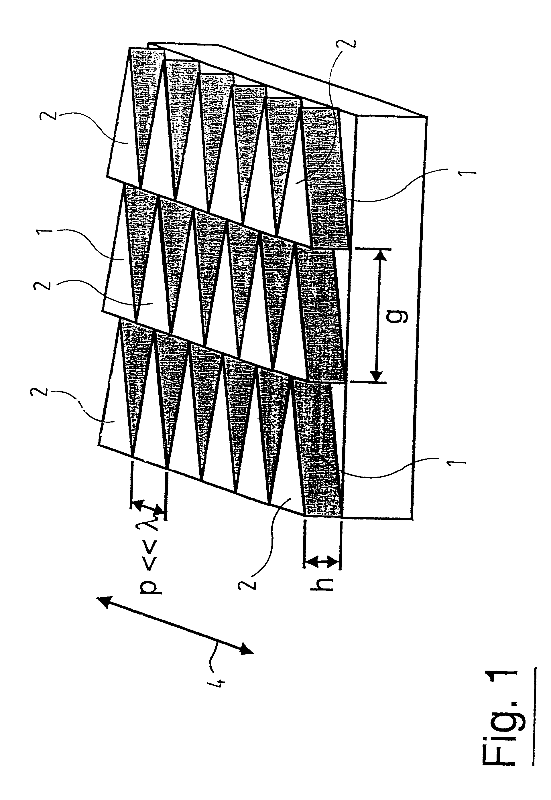
[0052]The blazed phase grating represented in FIG. 1 consists of a transmissive material with a refractive index n1. On the surface pointing upwards, it bears a multiplicity of parallel diffraction structures 1 extending in a straight line, three of which are shown as details in the drawing. The diffraction structures 1 have a width g perpendicular to their longitudinal direction. Since the diffraction structures 1 are directly next to one another, their width g corresponds to the conventional grating constant. In order to be able to achieve diffraction effects, the size of g is greater than the effective wavelength λ of the electromagnetic radiation for which the phase grating is intended, in the material with the refractive index n1. The effective wavelength λ is in this case given by

λ=λv / n1,

where λv is the wavelength in a vacuum.

[0053]Every diffraction structure 1 is in turn made up of a multiplicity of individual substructures 2 placed directly next to one another, each of which...


PUM

PropertyMeasurementUnit
refractive indexaaaaaaaaaa
thicknessaaaaaaaaaa
widthaaaaaaaaaa

Abstract

A diffractive optical element contains a multiplicity of binary blazed diffraction structures, which substantially extend mutually parallel in a longitudinal direction. Perpendicularly to the longitudinal direction, the diffraction structures have a width g which is greater than the effective wavelength of electromagnetic radiation for which the diffractive optical element is designed. The diffraction structures respectively comprise a series of individual substructures, which produce a blaze effect and have a maximum extent p in the longitudinal direction which is less than the effective wavelength of the electromagnetic radiation, at least on average over a diffraction structure. In a plan view, the individual substructures respectively have the shape of a closed geometrical surface, which has an extent parallel to the longitudinal direction that varies perpendicularly to the longitudinal direction. Perpendicularly to the longitudinal direction, the surface has a maximum extent which is greater than the effective wavelength.

Description

BACKGROUND OF THE INVENTION[0001]1. Field of the Invention[0002]The invention relates to a diffractive optical element having a multiplicity of binary blazed diffraction structures. The diffractive optical element is particularly intended for use in microlithographic projection exposure apparatus.[0003]2. Description of the Prior Art[0004]Conventional blazed gratings have diffraction structures of triangular, in particular sawtoothed cross section which extend mutually parallel with a spacing equal to the grating constant g. One edge of the diffraction structures, the blaze edge, has an inclination with respect to the base surface of the grating such that the reflection or refraction law is satisfied for one diffraction order of the incident light, and the majority of the intensity of the diffracted light is therefore contained in the order favoured by the blaze edge. The traditional method of producing such blazed gratings consisted in scratching the diffraction structures in a mas...

Claims


Application Information

Patent Timeline
Patent Type & Authority Patents(United States)
IPC IPC(8): G02B5/18G02B27/00G02B27/44G03F7/20
CPCG02B5/18G02B5/1809G03F7/70316G02B27/0043G02B5/1866
Inventor ARNOLD, RALFKLEEMANN, BERND
Owner CARL ZEISS SMT GMBH
Why Eureka
Try Eureka