Configurable terminal engine

a terminal engine and configuration technology, applied in the field of wireless communication systems, can solve the problems of low power advantage of asic, high cost of practice, and inability to meet the needs of asic,

Inactive Publication Date: 2006-11-21
MORPHICS TECH +1
View PDF22 Cites 30 Cited by
  • Summary
  • Abstract
  • Description
  • Claims
  • Application Information

AI Technical Summary

Problems solved by technology

Generally, each of these applications utilizes unique and incompatible modulation techniques and protocols.
This practice can be costly in terms of design, testing, manufacturing, and infrastructure resources.
On the other hand, the DSP provides greater flexibility since it is programmable but it does not offer the low power advantage of the ASIC.

Method used


Image

  • Configurable terminal engine
  • Configurable terminal engine
  • Configurable terminal engine

Examples


Embodiment Construction

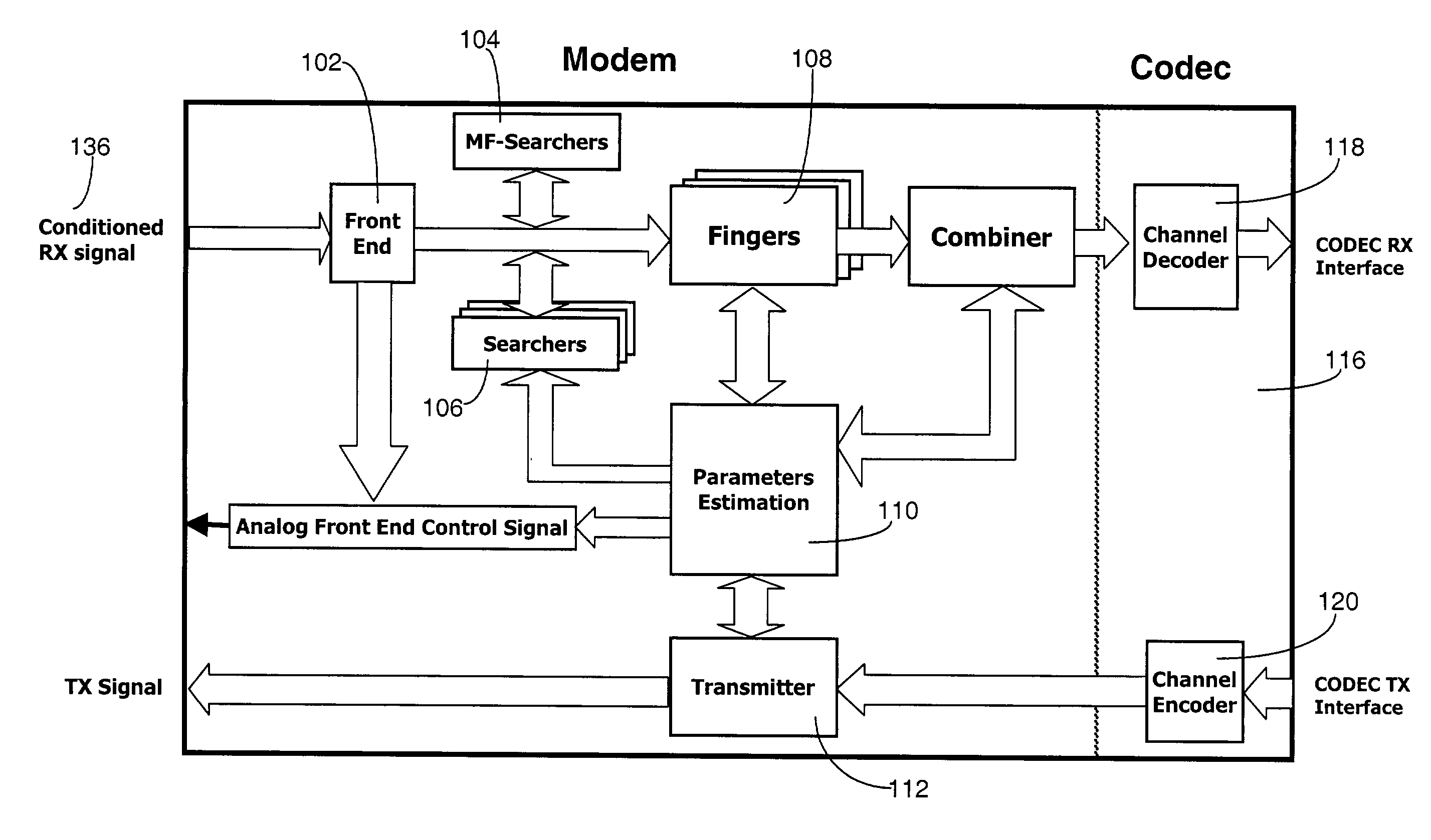
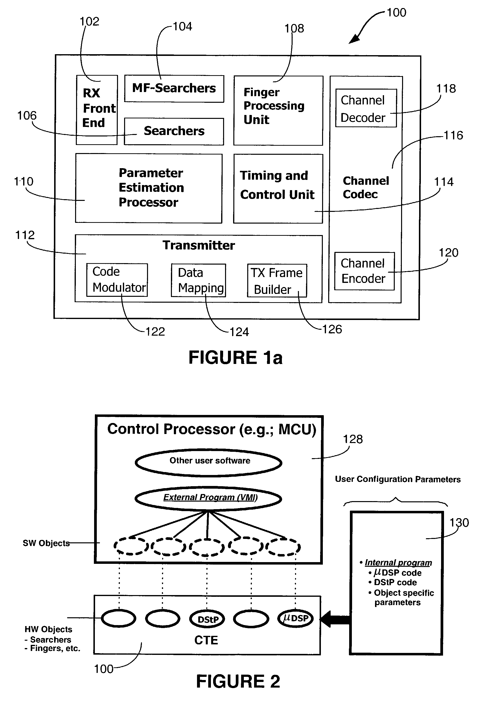
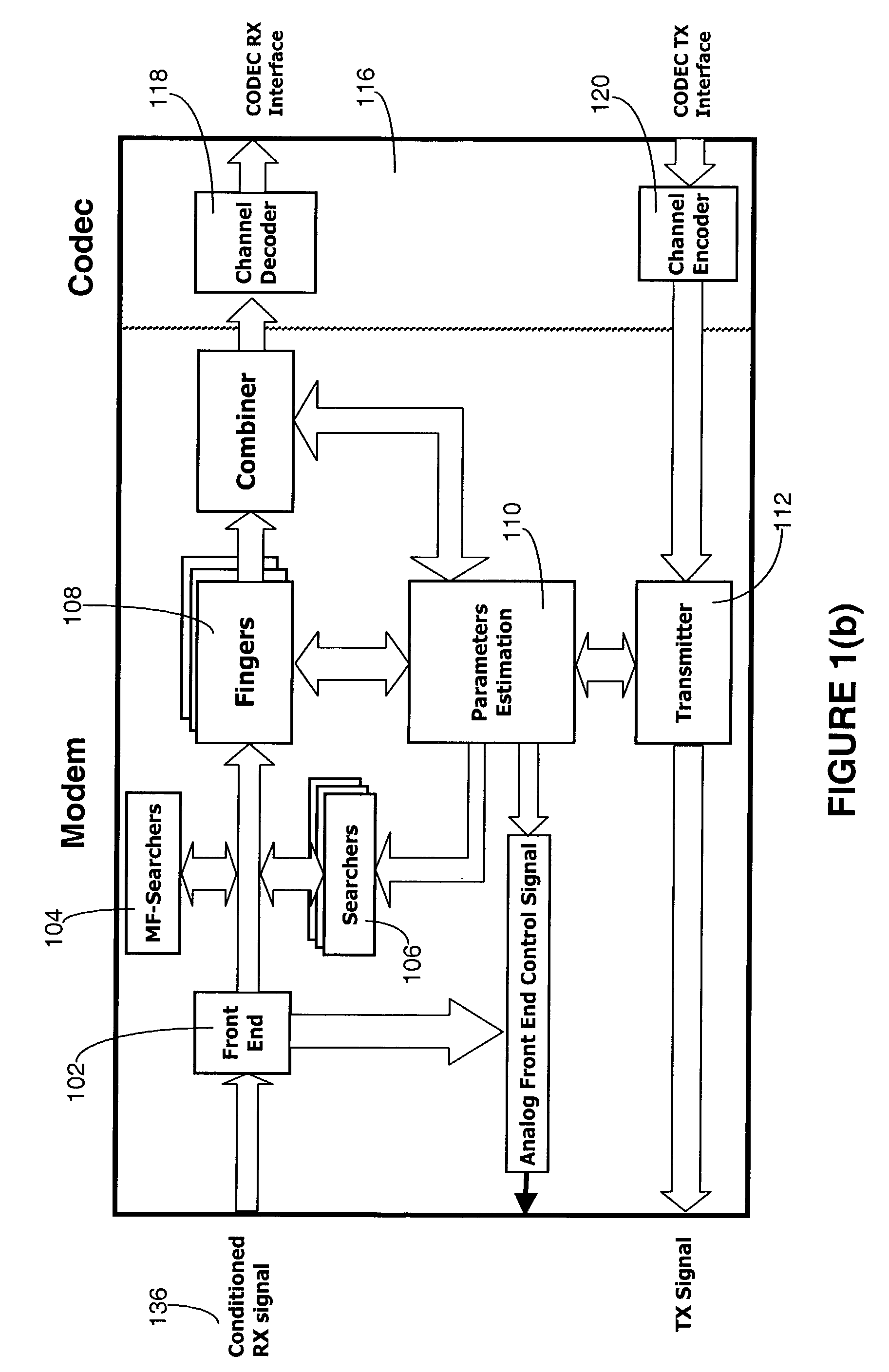
[0049]A Configurable Terminal Engine (CTE) 100 is shown in block diagram form in FIG. 1(a). The CTE is a programmable Direct-Sequence Spread Spectrum (DS-SS) Waveform Processing Engine. This DS-SS signal processor supports complete digital baseband transceiver functionality for multiple standards. These multiple standards include: 3GPP-FDD, IS-2000-1X (including IS-95A & IS-95B), ARIB W-CDMA, GPS, 802.11b, and various proprietary systems.

[0050]As shown in FIG. 1(a), the CTE 100 includes an RX front end 102, matched filter (MF) searchers 104, searchers 106, finger processing unit 108, parameter estimation processor 110, and transmitter 112. The CTE 100 also has a timing and control unit 114 and a channel codec 116 that includes channel decoder 118 and channel encoder 120. The transmitter 112 has a code modulator 122, data mapping 124 and TX frame builder 126. All the component units in FIG. 1 except for the channel codec 116 constitute the modem of CTE 100.

[0051]The CTE 100 is provid...


PUM


Abstract

A configurable cellular terminal engine (CTE) in accordance with an exemplary embodiment of this invention is configurable by an external agent (e.g., microcontroller, DSP, or state machine) to suit the particular requirements of different spread spectrum systems. In an exemplary embodiment, the CTE comprises on a chipset a modem unit and a channel codec unit. The modem unit has a front end unit for coupling to an antenna; a matched filter searchers unit coupled at least to the front end unit; a searchers unit coupled to at least the front end unit; a finger processing unit coupled to the front end unit; a parameter estimation processor unit coupled to at least the finger processing unit and the searchers unit; and a transmitter unit. The channel codec unit has a channel decoder unit coupled at least to the finger processing unit; and a channel encoder coupled at least to the transmitter unit.

Description

PRIORITY DATA[0001]This application claims priority from the following Provisional Application:[0002]“Configurable Terminal Engine,” bearing U.S. Ser. No. 60 / 310,193, filed on Aug. 2, 2001.CROSS REFERENCE TO RELATED APPLICATIONS[0003]Related applications are:[0004]“Apparatus and Method for Configurable Multi-dwell Search Engine for Spread Spectrum Applications”, Ser. No. 09 / 919,700, filed Jul. 31, 2001 now issued as U.S. Pat. No. 7,003,015 on Feb. 21, 2006;[0005]“Method and Apparatus for Time-sliced and Multi-threaded Data Processing in a Communication System”, Ser. No. 09 / 920,093, filed Jul. 31, 2001;[0006]“Apparatus and Methods for Sample Selection and Reuse of Rake Fingers in Spread Spectrum Systems”, Ser. No. 09 / 920,095, filed Jul. 31, 2001;[0007]“Distributed Micro Instruction Set Processor Architecture for High-efficiency Signal Processing”, Ser. No. 09 / 912,721, filed Jul. 24, 2001; and[0008]“Virtual Machine Interface for Hardware Reconfigurable and Software Programmable Proces...

Claims


Application Information

Patent Timeline
Patent Type & Authority Patents(United States)
IPC IPC(8): H04B1/69H04B1/40H04B1/707H04B1/7075H04B1/7093H04B1/7115
CPCH04B1/707H04B1/7075H04B1/7093H04B1/7115H04B2201/7071
Inventor GAVNOUDIAS, STRATISBOCCUZZI, JOSEPHJACQUES, ALEXANDERMISRA, RAJ M.ZHANG, YANSILVERBERG, AVIRIZZA, RICHARDNACSON, YOSEF
Owner MORPHICS TECH
Why Eureka
Try Eureka