
Precision variable area flowmeter apparatus

a flowmeter and variable area technology, applied in the field of variable area flowmeters, can solve the problems of increasing difficulty, rotameters without a signal transmission means are often unsatisfactory, and the visual reading of rotameters is difficult, so as to achieve the effect of increasing reliability and functional accuracy

Inactive Publication Date: 2006-11-28
VAUGHN TONI CLINE +1
View PDF16 Cites 11 Cited by
  • Summary
  • Abstract
  • Description
  • Claims
  • Application Information

AI Technical Summary

Benefits of technology

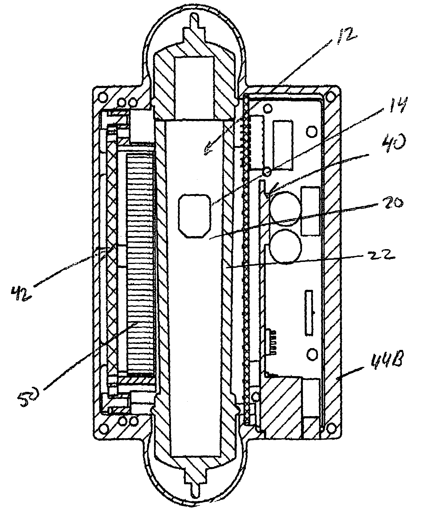
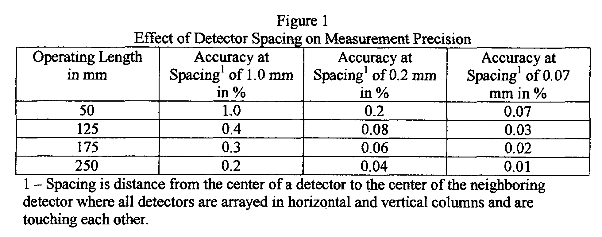
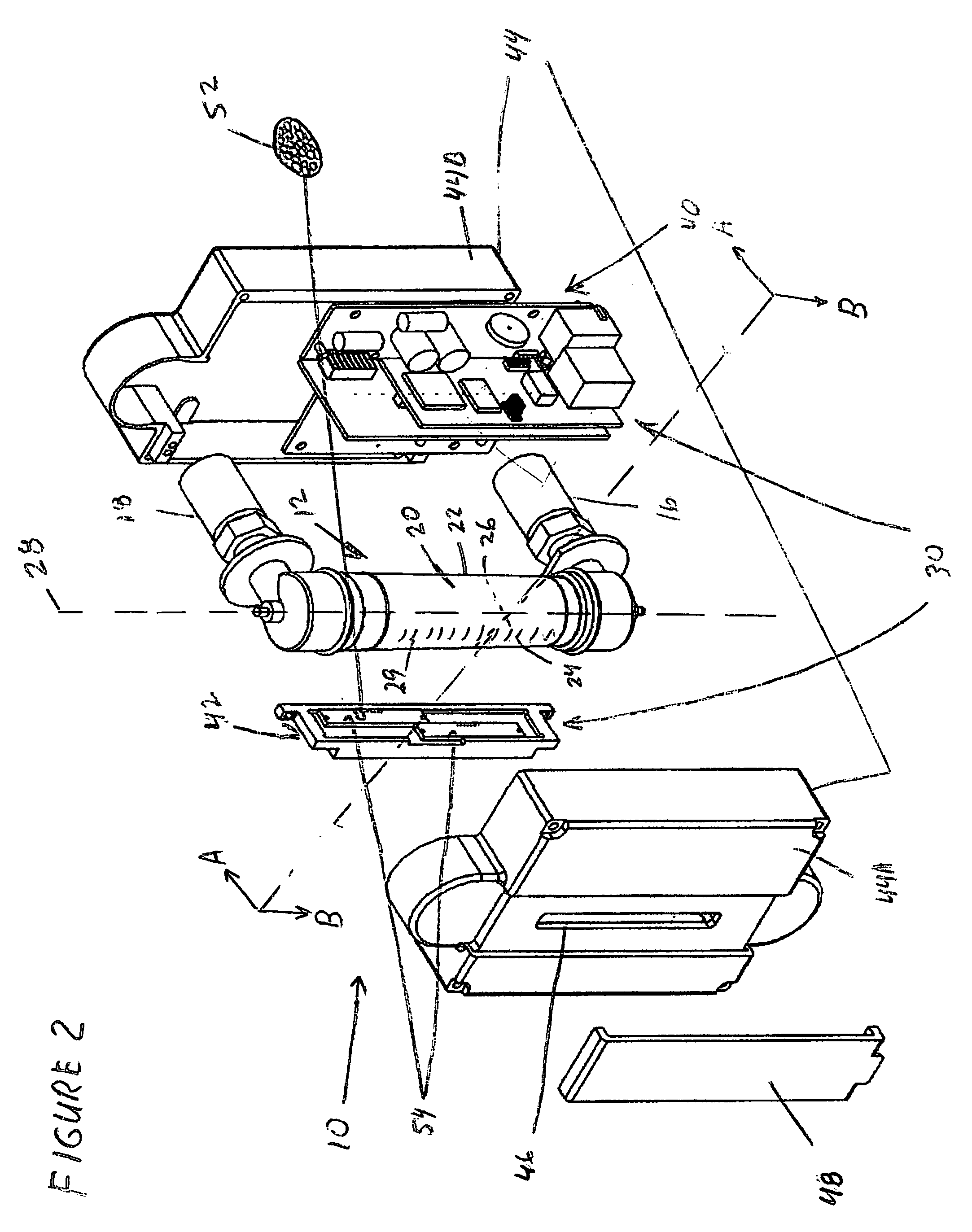
[0006]One embodiment of the detection means includes a detection means inside an isolated housing having an inside and an outside and encompassing the front and back side of the chamber. Optionally, the housing minimizes adverse influence of ambient radiation. The radiation detection means is temperature-insensitive, stationary, and able to directly monitor the position over the operational length of the chamber. The radiation detection means includes a radiation emitting source proximate to the front side and aligned substantially parallel to the long axis. The radiation detection means also includes a radiation detection assembly comprising a collection of radiation detectors separated from neighboring detectors by a distance 1.0 mm or less from neighboring detectors. The assembly is proximate to the back side and aligned substantially parallel to the long axis.
[0007]Another embodiment includes a collimator in the radiation detection assembly for minimizing the effect of radiation between the variable area flowmeter and the collection of radiation detectors coming into the detectors at angles not substantially perpendicular to the long axis.
[0010]The invention has many benefits relating to increased reliability, versatility and functional accuracy. Many variable area flowmeters have moving parts or intrusive design features that may be a source of leaks. The invention has no moving parts and is not intrusive so mechanical malfunction and unwanted leaks can not occur. Other flowmeters directly measure float positions but use part shadows and fiber optic extensions. In contrast, the invention directly measures float position over the entire operating range of the flowmeter. Still other flowmeters have functional accuracy no better than that obtainable with visual devices. The apparatus of the invention has functional accuracy that is at least under 1.0% and may be much lower depending on the operational length of the flowmeter and the specific radiation detectors used. In addition, some embodiments of the invention are able to measure float position in visually-opaque fluids. Additional benefits will become apparent as several embodiments are disclosed.

Problems solved by technology

One of the limitations has been that rotameters must be visually read in order to determine a flow rate and totalizing was estimated by multiplying the observed flow rate by a time interval.
Also, when totalization is needed, rotameters without a means of transmitting a signal are frequently unsatisfactory.
These difficulties have become more serious in recent years with an increased need for greater reliability and precision.
However most of theses systems are at least partly mechanical and contain moving parts that decrease reliability because they are exposed to mechanical failures.
One, using Charged Coupled Device (CCD) technology has an inherently limited physical range of use that increases system complexity and reduces precision.
Another, employing a float shadow detection means and widely spaced light sensors requires complex programming and circuit design and does not achieve precision greater than that available by visually monitoring a graduated scale on the chamber of the flowmeter.

Method used


Image

  • Precision variable area flowmeter apparatus
  • Precision variable area flowmeter apparatus
  • Precision variable area flowmeter apparatus

Examples


Embodiment Construction

[0024]We have invented an improved apparatus for measuring fluid flow that is superior to those known to the art. The apparatus electronically monitors the position of a flow indicator in a variable area flowmeter and includes the flowmeter and radiation detection means for determining location of the flow indicator. While the invention may be used on existing flowmeters and thus may be sold independently of a flowmeter, the following discussion will be about embodiments that include a flowmeter, whether as part of the apparatus or used in combination with electronic detection means invention. The flowmeter generally includes the flow indicator in a tapered fluid flow chamber with a wall and a long axis, the chamber having a front side, a back side, and an operational length substantially parallel to the long axis. These flowmeters are known to the art and have been used in one form or another for many years.

[0025]Our invention also includes a radiation detection means for measuring...


PUM


Abstract

We have invented an improved apparatus for electronically measuring fluid flow. The apparatus includes a radiation detection means for indicating the position of a flow indicator in a chamber of a variable area flowmeter and has a reliability, versatility and functional accuracy not obtainable with known variable area flowmeters. The invention may also include a variable area flowmeter with the flow indicator in a tapered fluid flow chamber with a wall and a long axis, the chamber having a front side, a back side, and an operational length substantially parallel to the long axis. The invention has no moving parts and is not intrusive so mechanical malfunction and unwanted leaks can not occur. Useful embodiments include, for example, compact self contained apparatus useful for fitting around existing flowmeters, systems that include flowmeters and systems able to work with some fluids that are visually opaque.

Description

FIELD OF THE INVENTION[0001]The present invention relates to variable area flowmeters and, more particularly, to providing an electronic output of flow data from such flowmeters.BACKGROUND OF THE INVENTION[0002]Variable area flowmeters also known as rotameters have been used as a flow rate monitoring device for several hundred years. One of the limitations has been that rotameters must be visually read in order to determine a flow rate and totalizing was estimated by multiplying the observed flow rate by a time interval. The accuracy of the results was dependent on a correct calibration of the rotameter and an assumption that that the flow rate remained constant over the time interval used in the calculation. When rotameters are used in industry, flow rates can and do vary considerably. Also, when totalization is needed, rotameters without a means of transmitting a signal are frequently unsatisfactory. These difficulties have become more serious in recent years with an increased nee...

Claims


Application Information

Patent Timeline
Patent Type & Authority Patents(United States)
IPC IPC(8): G01F1/22
CPCG01F1/22
Inventor VAUGHN, LEGAL REPRESENTATIVE, TONI CLINENEHER, NORMAN T.VAUGHN, DECEASED, TIMOTHY B.
Owner VAUGHN TONI CLINE
Learn More