Pneumatic tire and tire cavity resonance suppression device

a technology of cavity resonance and pneumatic tires, which is applied in the direction of machines/engines, instruments, transportation and packaging, etc., can solve the problems of deterioration of rim assembling performance, insufficient noise reduction effect, and rim assembling performance, so as to reduce cavity resonance and shorten resonance time , the effect of effective reduction of nois

Active Publication Date: 2006-11-28
MITSUBISHI MOTORS CORP +1
View PDF7 Cites 10 Cited by
  • Summary
  • Abstract
  • Description
  • Claims
  • Application Information

AI Technical Summary

Benefits of technology

[0005]A purpose of the present invention is to provide a pneumatic tire and a tire cavity resonance suppression device in which noise by cavity resonance can be effectively reduced without any changes in tire and rim production facilities.
[0008]According to the present invention, the object changed in sectional area in accordance with the position in the tire circumferential direction is housed in a cavity of the tire and fixed to the tread inner surface by the ring-shaped jig. Accordingly, a cavity resonance frequency is constantly changed with rotation of the tire to shorten time of resonance at the same frequency. Thus, it is possible to effectively reduce noise caused by cavity resonance. Moreover, the invention can be applied to existing tires without any changes in tire and rim production facilities.

Problems solved by technology

A cavity resonance phenomenon that occurs in a cavity formed between a tire and a wheel rim is a major factor of tire noise.
However, since the sound absorbing material is not basically designed to suppress the generation of cavity resonance, a sufficient noise reduction effect cannot be obtained by the sound absorbing material that can be fixed in the tire in practice.
Besides, the fixing of the shield to the rim has a problem that rim assembling performance is deteriorated.
However, a change in a structure of the tire or the rim is required in this method.
Moreover, it is difficult to apply the method to the existing tires or rims.

Method used


Image

  • Pneumatic tire and tire cavity resonance suppression device
  • Pneumatic tire and tire cavity resonance suppression device
  • Pneumatic tire and tire cavity resonance suppression device

Examples


example

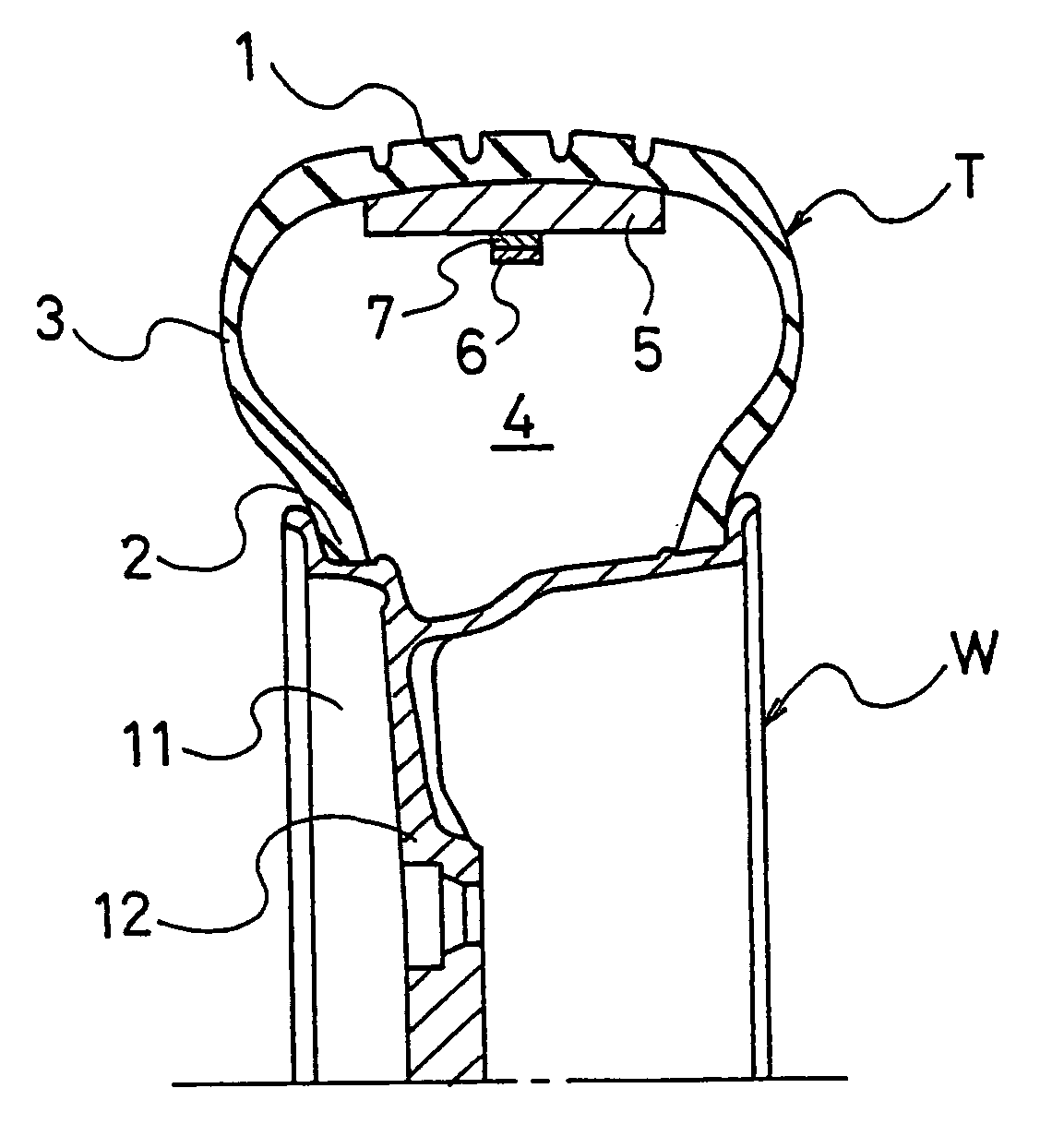
[0028]Regarding a pneumatic tire of a size 165 / 65R15, a conventional tire and a tire of the invention were manufactured by changing only cavity conditions as follows.[0029]Conventional tire:[0030]Nothing was arranged in the cavity.[0031]Tire of the invention:

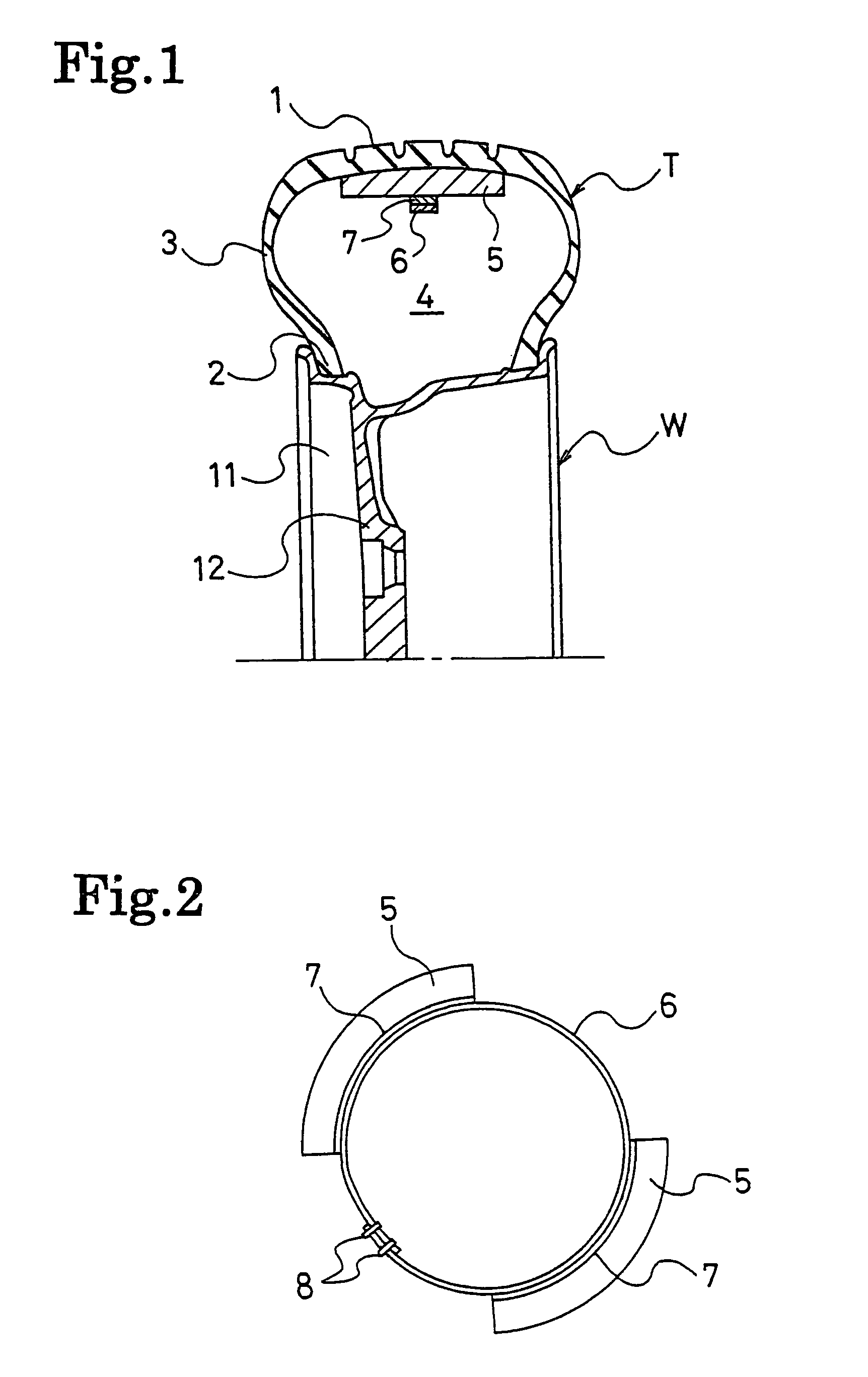
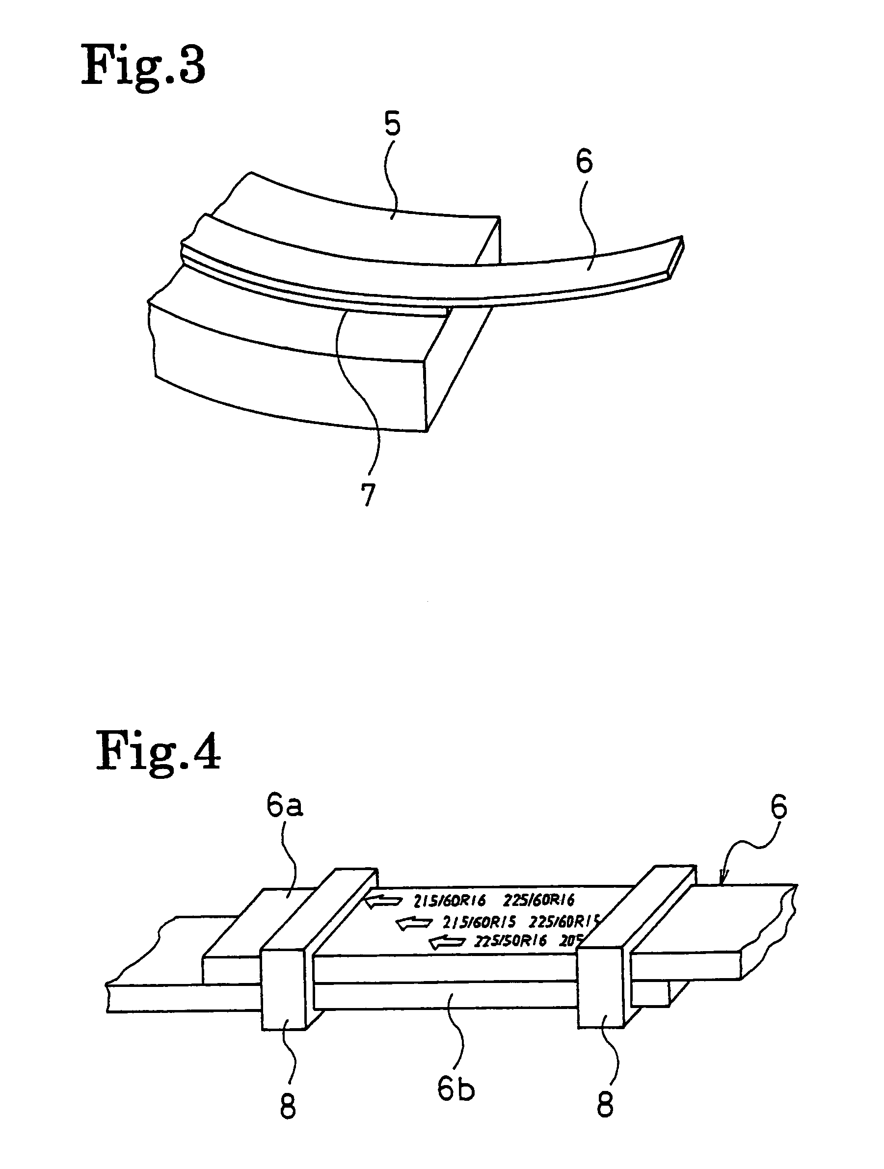
[0032]A plurality of objects (see FIGS. 1, 2) were fixed to a tread inner surface at equal intervals in a tire circumferential direction by using a ring-shaped jig made of an elastic body, and a sectional area changing rate of the cavity was 5.0% in the tire circumferential direction.

[0033]These tires were fit to wheels of rim sizes 15×5J, and axial force response levels [dB(N)] in a frequency range of 0 Hz to 350 Hz were obtained at axle positions by an impulse excitation method. The results are shown in FIG. 5.

[0034]As shown in FIG. 5, cavity resonance sound is generated in a band of about 200 Hz to 250 Hz in the conventional tire while cavity resonance sound is greatly reduced in the same band in the tire of the invention.

[00...


PUM

PropertyMeasurementUnit
specific gravityaaaaaaaaaa
sectional areaaaaaaaaaaa
specific gravityaaaaaaaaaa

Abstract

Disclosed are a pneumatic tire and a tire cavity resonance suppression device in which noise by cavity resonance is effectively reduced without any changes in tire and rim production facilities. The pneumatic tire is constituted by that an object, which is changed in sectional area in accordance with a position in a tire circumferential direction, is fixed to a tread inner surface by a ring-shaped jig made of an elastic body. The tire cavity resonance suppression device includes an object changed in sectional area in accordance with a position in a tire circumferential direction and a ring-shaped jig made of an elastic body for locking the object to a tread inner surface of the tire.

Description

BACKGROUND OF THE INVENTION[0001]The present invention relates to a pneumatic tire and a tire cavity resonance suppression device, and more particularly, to a pneumatic tire and a tire cavity resonance suppression device in which noise caused by cavity resonance is effectively reduced.[0002]A cavity resonance phenomenon that occurs in a cavity formed between a tire and a wheel rim is a major factor of tire noise. For example, the cavity resonance phenomenon is concerned with noise around 250 Hz regularly heard during traveling or impulsive sound generated driving over gaps or the like of on a road.[0003]As a technique for reducing noise caused by such a cavity resonance phenomenon, addition of a sound absorbing material in the tire to absorb resonance sound, and fixing of a shield to the rim to subdivide the cavity have been proposed. However, since the sound absorbing material is not basically designed to suppress the generation of cavity resonance, a sufficient noise reduction eff...

Claims


Application Information

Patent Timeline
Patent Type & Authority Patents(United States)
IPC IPC(8): B60C5/12B60C19/00B60C5/00B60R13/08G10K11/16G10K11/172
CPCB60C19/002G10K11/172B60R13/08Y10T152/10054Y10T152/10117Y10T152/10495
Inventor TANNO, ATSUSHI
Owner MITSUBISHI MOTORS CORP
Why Eureka
Try Eureka