

Fluid filled vibration damping device
a technology of vibration damping device and fluid filling, which is applied in the direction of shock absorbers, jet propulsion mountings, machine supports, etc., can solve the problems of difficulty in producing a reaction force against a tightening torque of the connecting bolt, the aforesaid structure still suffers, and the fluid filling vibration damping device can not be used in the field of fluid filling vibration damping device, so as to improve the degree of freedom in design choice of mounting projection, prevent or minimiz
- Summary
- Abstract
- Description
- Claims
- Application Information
AI Technical Summary
Benefits of technology
Problems solved by technology
Method used
Image

Examples
first embodiment
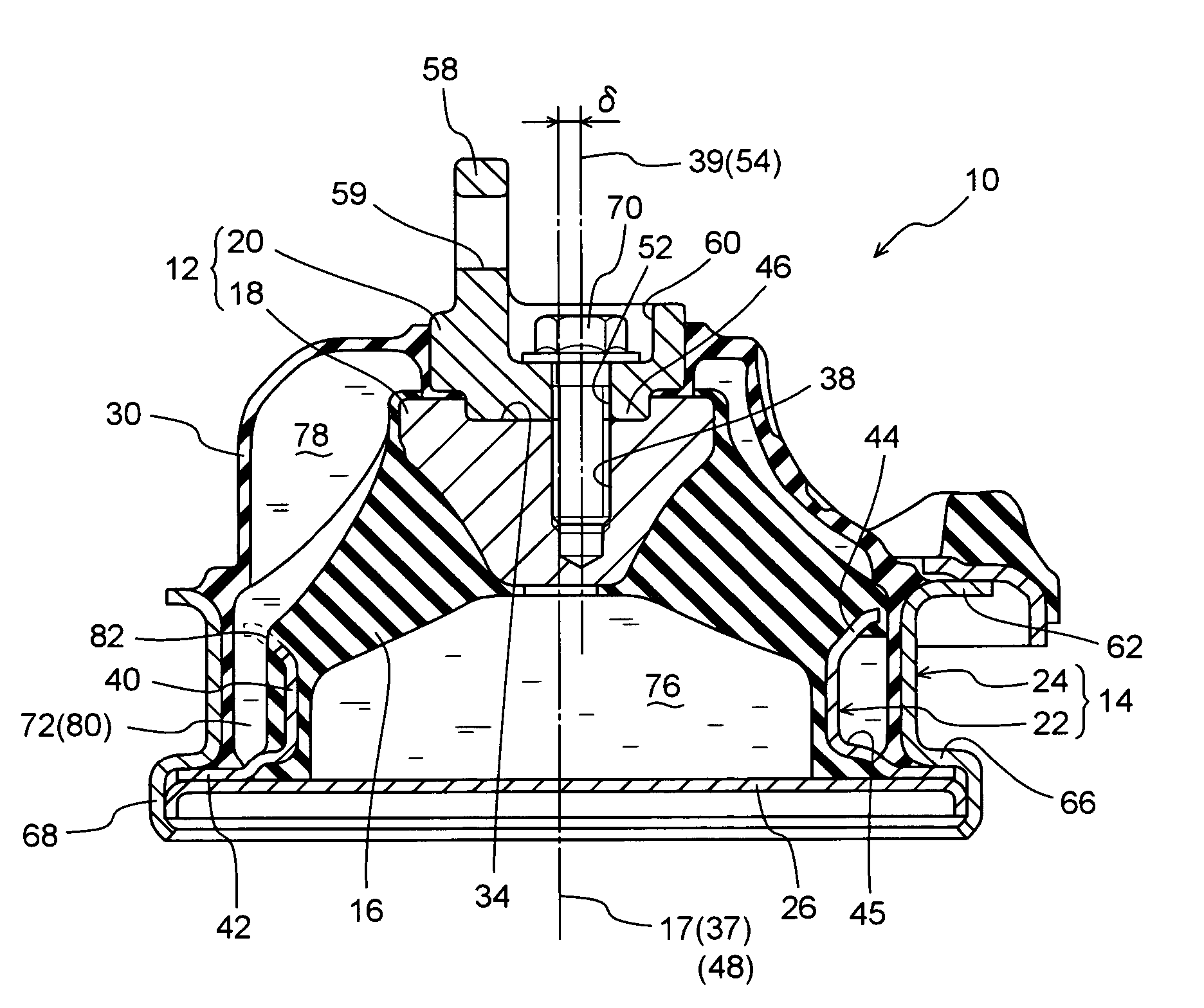
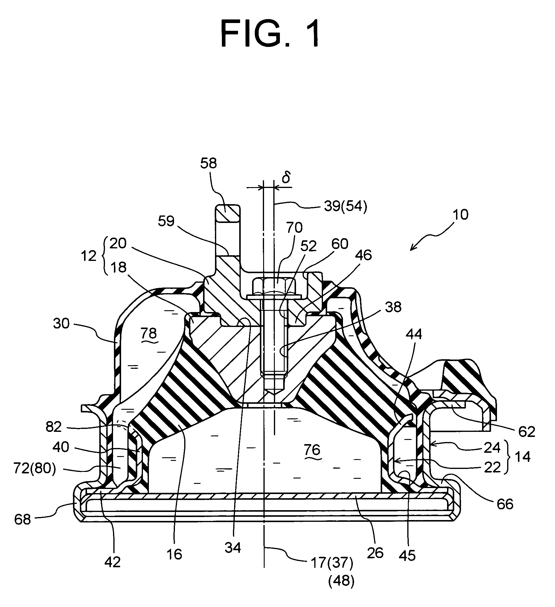
[0031]Referring first to FIGS. 1–2, shown is a fluid filled vibration damping device in the form of an engine mount 10 constructed according to the present invention. The engine mount 10 includes a first mounting member 12 and a second mounting member 14 which are both made of metal, and are elastically connected to each other via a rubber elastic body 16 interposed therebetween. With the first mounting member 12 fixed to a power unit (not shown) of the vehicle, and the second mounting member 14 fixed to a body (not shown) of the vehicle, the engine mount 10 can support the power unit on the body of the vehicle in a vibration damping fashion. With the engine mount 10 installed in position as described above, an initial load or weight of the power unit as well as a vibrational load to be damped are primarily applied between the first and second mounting members 12, 14 in an approximately axial direction of the engine mount 10, i.e., the vertical direction as seen in FIG. 1. In the fo...
second embodiment
[0064]The illustrated engine mount 10 may desirably incorporate a variety of known mechanism or devices, depending on required vibration damping characteristics. For instance, an auxiliary fluid chamber 86 may be added to the engine mount 10, as shown in FIG. 6. Namely, on the side of the lid member 26 opposite from the pressure receiving chamber 76, is formed the auxiliary fluid chamber 86 partially defined by a rubber elastic wall 85 and filled with the non-compressible fluid. The auxiliary fluid chamber 86 has a wall spring stiffness smaller than does the pressure-receiving chamber 76 and larger than does the equilibrium chamber 78, and a second orifice passage 88 is formed to permit a fluid communication between the pressure-receiving chamber 76 and the auxiliary fluid chamber 86. The second orifice passage is tuned to a higher frequency band than does the orifice passage 80. Thus, is provided an engine mount 90 constructed according to the invention. In the engine mount 90, the...
third embodiment
[0065]Alternatively, an active vibration damping mechanism may be added to the engine mount 10, as shown in FIG. 7. Namely, instead of the lid member 26, an oscillating plate 92 of generally disk shape is disposed. The oscillating plate 92 is fixed at its peripheral end to an annular support member 94 via an annular plate-like support rubber 96. The annular support member 94 is fixed by caulking to the diaphragm-side outer sleeve member 24. On the axially lower side of the diaphragm-side outer sleeve member 24, there is disposed an actuator 98 of air pressure type, electromagnetic-type, or other various types, as indicated in two-dot chain line in FIG. 7. This actuator 98 is operable to oscillate the oscillating plate 92, thereby providing an engine mount 100 constructed according to the invention. In this engine mount 100, the oscillating plate 92 is operated under control so as to be oscillated at a frequency and phase corresponding to those in an input vibration. This makes it po...
PUM
 Abstract
Description
Claims
Application Information