Electric parking brake apparatus

a technology of parking brakes and friction components, which is applied in the direction of braking systems, brake components, brake pads, etc., can solve the problems of fading failure of disclosed apparatus to maintain the braking force of parking brake at a desired level, and high temperature of parking brake components, etc., to achieve the effect of reducing the friction coefficient of the friction surface of the friction member, preventing the drop of parking brake braking force stemming from fading, and reducing

Inactive Publication Date: 2006-11-28
ADVICS CO LTD
View PDF28 Cites 31 Cited by
  • Summary
  • Abstract
  • Description
  • Claims
  • Application Information

AI Technical Summary

Benefits of technology

[0039]As described previously, in the case where the parking brake is disposed at a location in the vicinity of a service brake of the vehicle such that heat generated by the service brake is transferred to the parking brake, when the temperature of the service brake increases, the temperatures of the components (rotation member and friction member) of the parking brake increase in a manner similar to that of the temperature of the service brake. Meanwhile, as the temperatures of the components of the parking brake increase, the friction coefficient of the friction surface of the friction member decreases as a result of fading, so that the brake force of the parking brakes decrease even when the pressure contact force of the friction member pressed against the rotation member is constant.
[0040]

Problems solved by technology

Accordingly, when the temperature of the service brake becomes high as a result of repeated use of the service brake during traveling of the vehicle, the temperatures of components (brake disk, brake pads, etc.) of the parking brake also become high, with resultant thermal expansions of the components.
However, the disclosed apparatus has the following problem.
As a result, the disclosed apparatus may fail to maintain the braking force of the parking brake at a desired level through the elapse of the predetermined time.
Moreover, in the case where the braking force of the parking brake drops because of a factor other than the temperature decreases of the components of the parking brake at a certain point in time after completion of the above-described pa

Method used


Image

  • Electric parking brake apparatus
  • Electric parking brake apparatus
  • Electric parking brake apparatus

Examples


Embodiment Construction

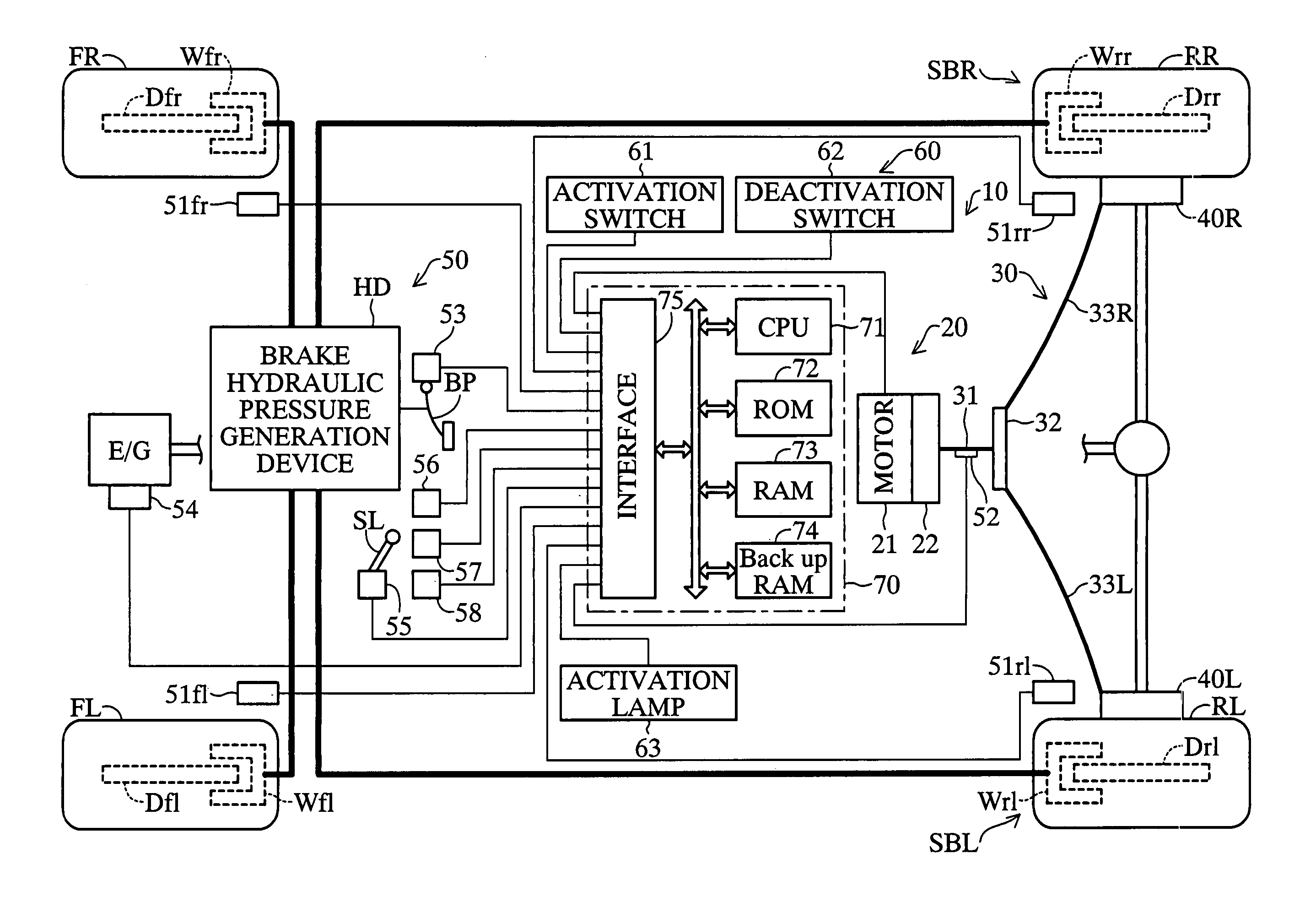
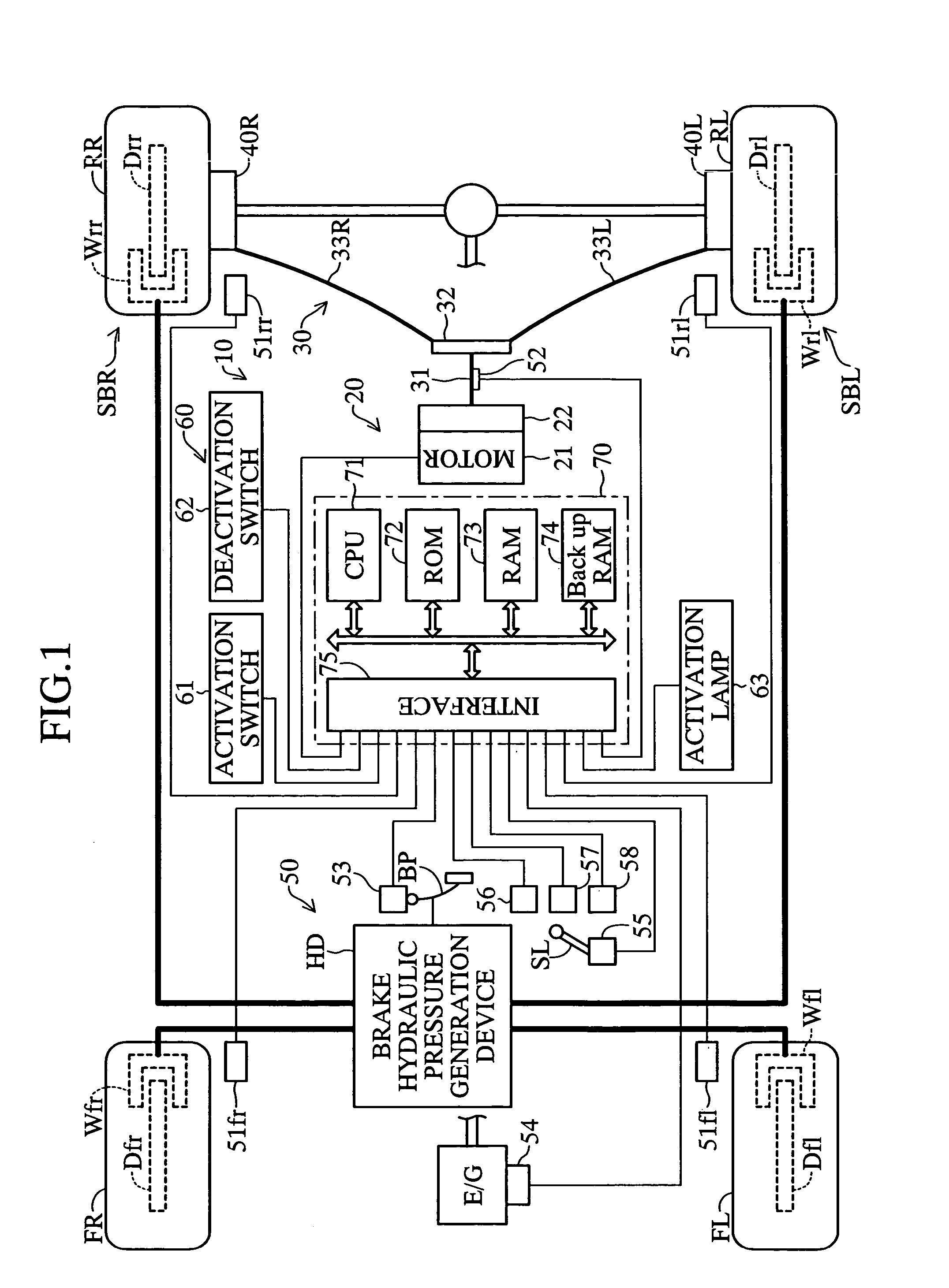
[0061]An embodiment of the present invention will now be described with reference to the drawings. FIG. 1 schematically shows the configuration of a vehicle on which is mounted an electric parking brake apparatus 10 according to the embodiment of the present invention. The vehicle is a four-wheel vehicle which has two front wheels (a front left wheel FL and a front right wheel FR) and two rear wheels (a rear left wheel RL and a rear right wheel RR).

[0062]The electric parking brake apparatus 10 includes a drive actuator section 20, a wire structure section 30, left-hand and right-hand parking brakes 40L and 40R provided adjacent to the two rear wheels, respectively, a sensor section 50, a switch-lamp system 60, and an parking brake control unit 70.

[0063]The drive actuator section 20 includes an electric motor 21, serving as electric drive means, and a speed reduction mechanism 22, serving as a force transmission blocking mechanism. The electric motor 21 can rotate in forward and reve...


PUM


Abstract

When a driver operates an activation switch, an electric parking brake apparatus performs a parking brake activation control in order to operate an electric motor until the tension of a base wire reaches a predetermined target tension to thereby bring parking brakes into an activated state. After that, the apparatus again performs the parking brake activation control when a re-activation time, which is set in accordance with the difference between an estimated temperature of a service brake and an ambient temperature, has elapsed; when the position of a shift lever has been changed; when the height of the vehicle has changed by an amount greater than a predetermined amount; or when the driver releases a brake pedal which has been continuously operated after completion of the parking brake activation control.

Description

BACKGROUND OF THE INVENTION[0001]1. Field of the Invention[0002]The present invention relates to an electric parking brake apparatus capable of operating a parking brake of a vehicle by use of electric drive means such as an electric motor.[0003]2. Description of Related Art[0004]Japanese Patent Application Laid-Open (kokai) No. 2002-225701 discloses a conventional electric parking brake apparatus of such a type. The disclosed apparatus includes a parking brake, which consists of a brake disk and a brake pad for generating a braking force corresponding to a pressure-contact force at the time of pressure contact with the brake disk; and an electric motor for driving the brake pad. Parking brake activation control is performed in such a manner that the motor is operated until current flowing through the motor and increasing with the pressure contact force reaches a predetermined target value, so as to bring the parking brake into an activated state in which the parking brake can stop ...

Claims


Application Information

Patent Timeline
IPC IPC(8): B60T13/66B60T7/02B60T7/10B60T7/12B60T13/74B60T17/22
CPCB60T7/107B60T7/12B60T13/66B60T13/746B60W30/18118B60W40/13B60W2510/10B60W2510/184B60W2710/18
Inventor KOGA, KEIICHITACHIIRI, YOSHIKAZU
Owner ADVICS CO LTD
Why Eureka
Try Eureka