Control system for an illumination device incorporating discrete light sources

a control system and light source technology, applied in the field of illumination control, can solve problems such as preventing the effective use of linear pid controllers

Active Publication Date: 2006-11-28
SIGNIFY HLDG BV
View PDF11 Cites 133 Cited by
  • Summary
  • Abstract
  • Description
  • Claims
  • Application Information

AI Technical Summary

Benefits of technology

[0012]An object of the present invention is to provide a control system for an illumination device incorporating discrete light sources. In accordance with an aspect of the present invention, there is provided an illumination system comprising: a plurality of light-emitting elements for providing illumination having a variety of wavelengths; at least one detecting device for providing information regarding the illumination being created by the light-emitting elements; a computing system for receiving the information from the at least one detecting device and based on a predetermined set of parameters, determining a plurality of control parameters; a controller for receiving the plurality of control parameters and determining a set of control signals, wherein said control signals are sent to the light-emitting elements in order to control the illumination being created; and a power source for providing power to the illumination system.

Problems solved by technology

However, this scenario introduces additional design issues such as variations in colour sensor spectral responsivities, sampling rates, and feedback loop response times. In addition, approximations are introduced by linear colour spaces when translating the sensor signals into a model of human colour vision, for the perceived illumination.
The combination of junction temperature dependencies, square law dimming, and colour space mapping may therefore preclude the effective use of linear PID controllers as is done in the prior art.

Method used


Image

  • Control system for an illumination device incorporating discrete light sources
  • Control system for an illumination device incorporating discrete light sources
  • Control system for an illumination device incorporating discrete light sources

Examples


example 1

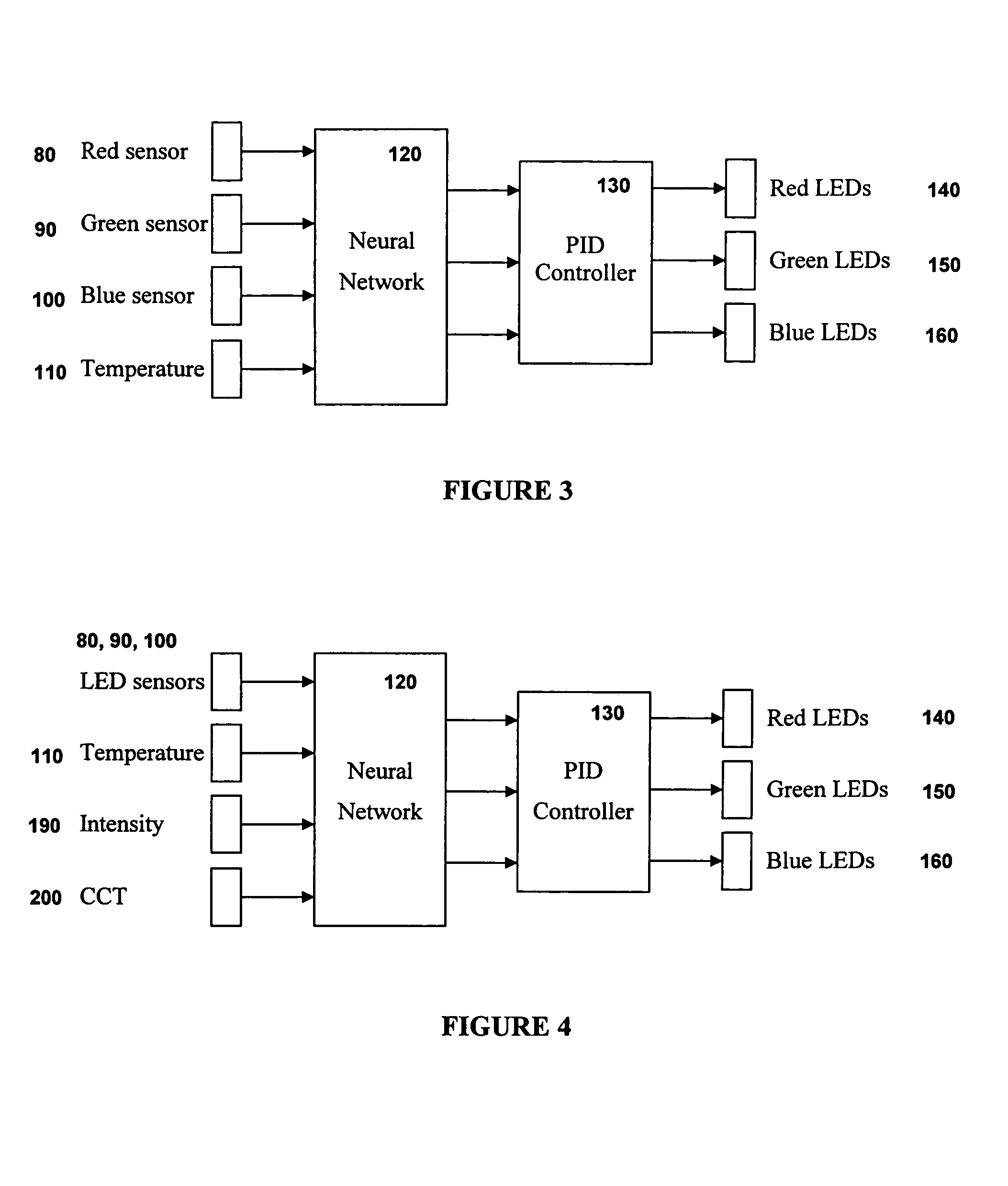
[0038]In one embodiment and with reference to FIG. 3, the illumination system comprises light-emitting elements producing illumination having colours of red 140, green 150 and blue 160, detecting devices enabling the evaluation of the illumination intensities of the colours red 80, green 90 and blue 100 together with information relating to the junction temperatures 110 of the light-emitting elements. The computing system is a neural network 120 which is trained with known input data and desired responses using supervised learning techniques such that it can automatically determine the non-linear multivariate function representing the desired hyperplane. In operation, the neural network essentially linearises the sensor signals as input to a conventional proportional integral-derivative (PID) controller 130 which provides the control signals, in the form of current variations to the light-emitting elements in order to maintain constant luminous intensity and chroma.

example 2

[0039]In another embodiment and with reference to FIG. 4, the illumination system comprises the elements outlined in Example 1, and further comprises detecting devices which enable the input of user requests regarding desired luminous intensity 190 and correlated colour temperature (CCT) 200. Optionally, an additional user-controlled input or detecting device can provide an indication of the desired chromaticity in a direction orthogonal to the blackbody locus to effect a desired change in tint of nominal “white” light without changing its correlated colour temperature, for example. In this embodiment, the neural network that is trained with appropriate known input data and desired responses such that the chroma is constrained to follow that of the blackbody locus in CIE 1976 u-v uniform chromaticity space to generate nominal “white” light at different correlated colour temperatures, or CCT.

example 3

[0040]In another embodiment and with reference to FIG. 5, the illumination system comprises the elements outlined in Example 1, and further comprises a further detection device in the form of a second colourimeter in order to monitor the intensity and approximate spectral distribution of ambient illumination due to the combination of the luminous flux emitted by the luminaire and daylight 220 and / or other light sources. In this embodiment, the neural network is trained such that the intensity and correlated colour temperature of the ambient illumination, or perceived lighting conditions which are a combination of the illumination from the illumination system and other sources, is held approximately constant or follows a user-defined correlation with the intensity and correlated colour temperature of daylight illumination. For example, if there was an increase in the ambient lighting conditions, due to an increase in the propagation of sunlight into an area, and based on the desired ...


PUM


Abstract

The present invention provides an illumination system enabling dynamic color control of the illumination produced by the system. The illumination system comprises light-emitting elements for producing illumination, and at least one detecting device which collects information relating to the illumination, which is inherently non-linear. The illumination system also integrates a computing system which receives the information from the at least one detecting device and linearises this information using a multivariate function having a solution defining a hyperplane representing constant chromaticity for a given luminous intensity, and then determines a number of control parameters based on the information. The illumination system also integrates a controller for receiving the control parameters from the computing system and determining the control signals to be sent to the light-emitting elements in order to dynamically alter the characteristics of the illumination based on the collected information and the desired illumination result.

Description

[0001]This application claims priority to U.S. Application No. 60 / 489,389, filed Jul. 23, 2003FIELD OF THE INVENTION[0002]The present invention pertains to the field of illumination control, and in particular to a control system for an illumination device incorporating discrete light sources.BACKGROUND[0003]Polychromatic light sources with independent intensity controls can offer the ability to generate any colour within the colour gamut of the constituent light sources. An example is a solid-state light fixture with red, green, and blue (RGB) light emitting diodes. There are a number of control systems that enable the control of a luminaire incorporating a plurality of different emission colour light sources. These control systems provide a means for the manipulation of the resultant blended illumination based on a desired illumination level.[0004]For example U.S. Pat. No. 5,350,977 discloses a luminaire of variable colour temperature which includes a plurality of light sources of ...

Claims


Application Information

Patent Timeline
Patent Type & Authority Patents(United States)
IPC IPC(8): F21V23/04H05B44/00H01L33/00
CPCH05B33/086H05B33/0869H05B33/0872Y02B20/341H05B45/22H05B45/28H05B47/11Y02B20/30Y02B20/40H05B45/20
Inventor ASHDOWN, IAN
Owner SIGNIFY HLDG BV
Why Eureka
Try Eureka