Permanent magnet synchronous machine

a permanent magnet, synchronous machine technology, applied in the direction of dynamo-electric machines, magnetic circuit shapes/forms/construction, electrical apparatus, etc., can solve the problems of increased losses, and achieve the effect of preventing the saturation effect of tooth head configuration and reducing installation heigh

Inactive Publication Date: 2006-11-28
SIEMENS AG
View PDF25 Cites 60 Cited by
  • Summary
  • Abstract
  • Description
  • Claims
  • Application Information

AI Technical Summary

Benefits of technology

[0008]A pitch ratio of tooth pitch to pole pitch of ≧2.5 and the alignment of the permanent magnets of the rotor in flux concentration of the rotor results in a flux density within the air gap that would cause the tooth heads to saturate. However, as a consequence of the configuration of the tooth heads saturation effects are prevented. Suitably, the tooth height of the tooth head is suited to the construction-dependent air gap flux density. This is necessary because the flux lines close across the tooth heads to neighboring permanent magnets. It is hereby not required to direct the flux line in the tooth pole or in the back of the stator yoke. As a result, novel solutions can constructively be pursued because there is no longer any need to construct the yoke and the tooth pole to suit such flux densities is eliminated. In other words, the tooth as well as the yoke can be made significantly narrower so that smaller installation heights can be realized.

Problems solved by technology

As a result, increased losses are experienced.

Method used


Image

  • Permanent magnet synchronous machine
  • Permanent magnet synchronous machine
  • Permanent magnet synchronous machine

Examples


Embodiment Construction

[0021]Throughout all the Figures, same or corresponding elements are generally indicated by same reference numerals. These depicted embodiments are to be understood as illustrative of the invention and not as limiting in any way. It should also be understood that the drawings are not necessarily to scale and that the embodiments are sometimes illustrated by graphic symbols, phantom lines, diagrammatic representations and fragmentary views. In certain instances, details which are not necessary for an understanding of the present invention or which render other details difficult to perceive may have been omitted.

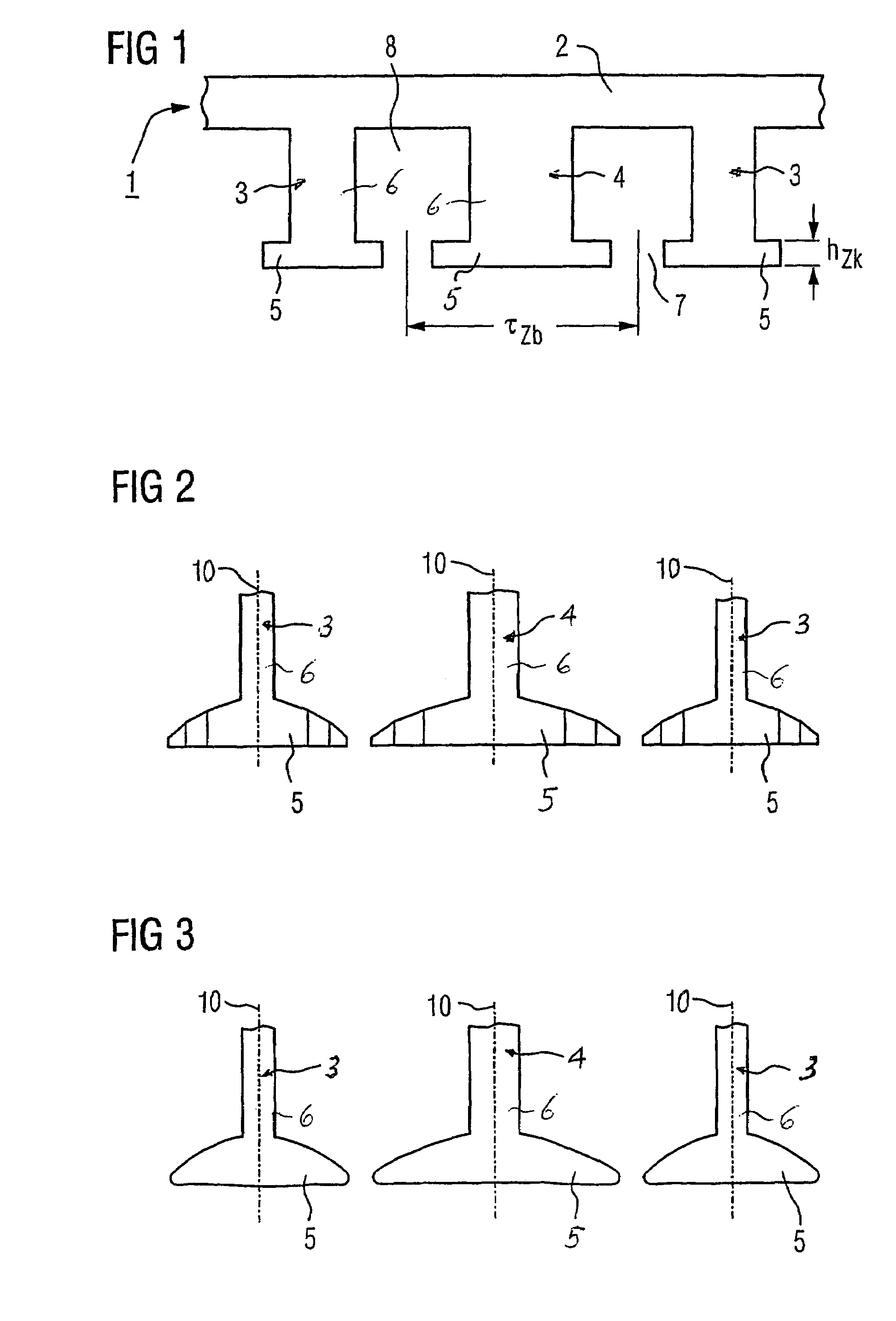
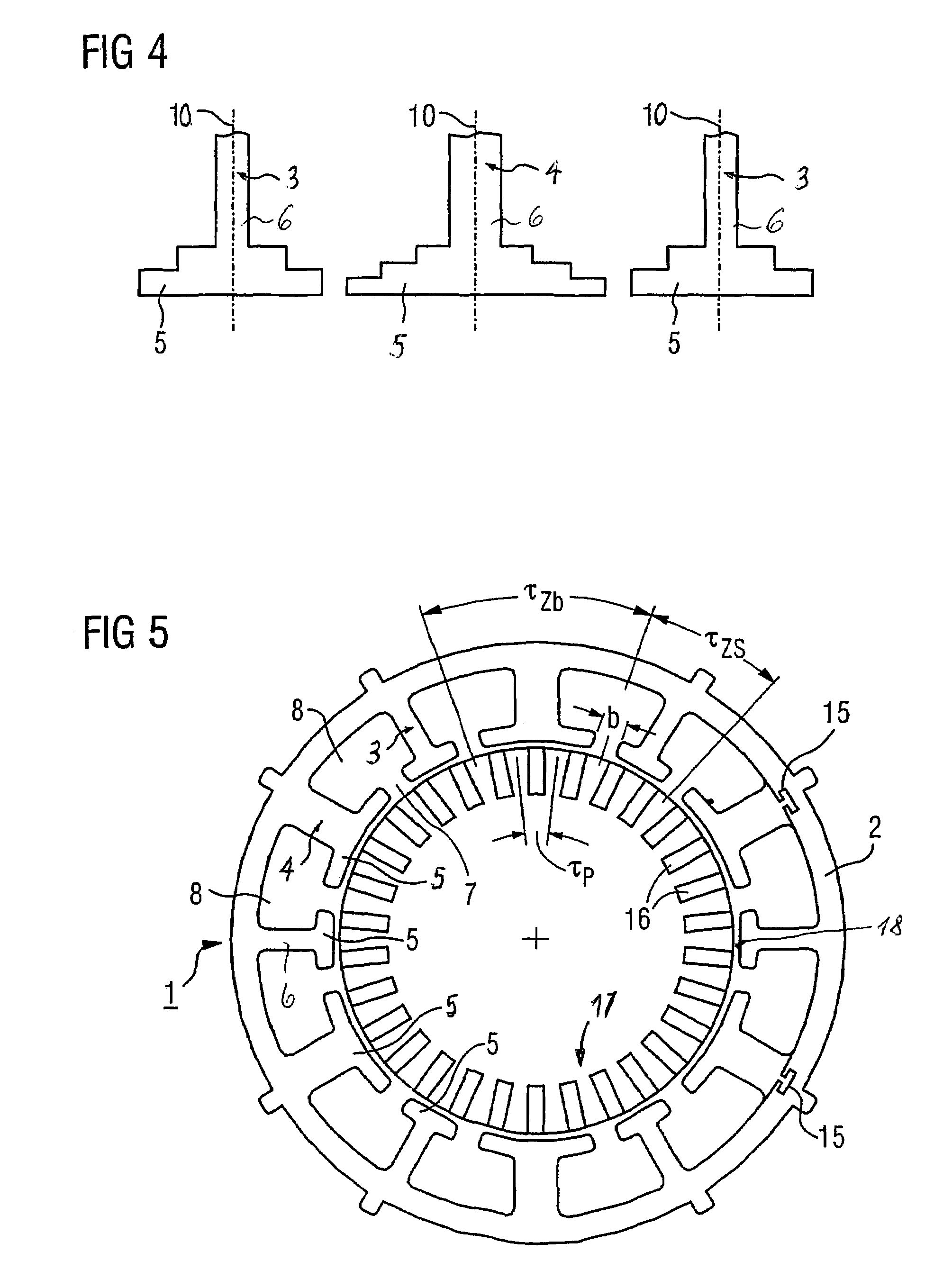
[0022]Turning now to the drawing, and in particular to FIG. 1, there is shown a fragmentary schematic illustration of a first variation of a stator, generally designated by reference numeral 1, for a permanent magnet synchronous machine according to the present invention. The stator 1 includes a stator yoke 2, and a first plurality of teeth 3 and a second plurality of teeth 4 ...


PUM


Abstract

A permanent magnet synchronous machine includes a stator, and a rotor which defines with the stator an air gap. The stator includes a plurality of teeth which are disposed in spaced-apart circumferential relationship and separated from one another by a tooth pitch. Each of the teeth has a shaft which terminates in a tooth head adjacent the air gap, with the tooth heads of neighboring teeth being separated from one another by a slot. The tooth heads are constructed to prevent saturation. The rotor has permanent magnets which are aligned in flux concentration direction and arranged to define a pole pitch, wherein a pitch ratio of tooth pitch to pole pitch is ≧2.5.

Description

CROSS-REFERENCES TO RELATED APPLICATIONS[0001]This application is a continuation of prior filed copending PCT International application no. PCT / DE2003 / 003364, filed Oct. 10, 2003, which designated the United States and on which priority is claimed under 35 U.S.C. §120 and which claims the priority of German Patent Application, Serial No. 102 48 771.5, filed Oct. 18, 2002, pursuant to 35 U.S.C. 119(a)–(d).BACKGROUND OF THE INVENTION[0002]The present invention relates, in general, to a permanent magnet synchronous machine.[0003]Nothing in the following discussion of the state of the art is to be construed as an admission of prior art.[0004]A permanent magnet synchronous machine of a type involved here includes a stator and a rotor which together define an air gap. The stator includes teeth which have each a radial tooth pole and an axially extending tooth head, whereby the tooth heads are arranged adjacent the air gap and neighboring tooth heads in circumferential direction are spaced...

Claims


Application Information

Patent Timeline
Patent Type & Authority Patents(United States)
IPC IPC(8): H02K1/00H02K1/14H02K21/16
CPCH02K1/146H02K21/16
Inventor VOLLMER, ROLF
Owner SIEMENS AG
Why Eureka
Try Eureka