Power supply circuit that is stable against sudden load change

a power supply circuit and load change technology, applied in the direction of electric variable regulation, process and machine control, instruments, etc., can solve the problems of increasing circuit size, increasing required electric power, increasing power fluctuation caused by circuit operation, etc., to increase the response speed of the operational amplifier, avoid the fluctuation of an input voltage, and stable power

Active Publication Date: 2006-11-28
FFC +1
View PDF12 Cites 16 Cited by
  • Summary
  • Abstract
  • Description
  • Claims
  • Application Information

AI Technical Summary

Benefits of technology

[0033]In this manner, the construction of the invention makes it possible to cope with a sudden change in the load by increasing the response speed of the operational amplifier. It is thus possible to provide stable power by keeping the output voltage constant against sudden changes in the load. Since the output voltage does not change, further, it is possible to avoid the fluctuation of an input voltage responding to a change in the load.

Problems solved by technology

Moreover, the fields of application have expanded, resulting in an increase of circuit size.
As the circuit size increases inside the IC cards, power fluctuation caused by circuit operations becomes large, and required electric power also increases.
There may thus be a risk of letting the operational amplifier 31 oscillate.
Because of this reason, it is difficult to cope with a sudden change in the load by enhancing the response speed of the operational amplifier 31.
If the load connected to the voltage VDDF shows a sudden change, the control of the voltage VDDF by the operational amplifier 31 may not be sufficiently fast, resulting in the voltage VDP on the input side being changed.

Method used


Image

  • Power supply circuit that is stable against sudden load change
  • Power supply circuit that is stable against sudden load change
  • Power supply circuit that is stable against sudden load change

Examples


first embodiment

[0050]FIG. 3 is a block diagram showing a power supply circuit according to the invention. In FIG. 3, the same elements as those of FIG. 1 are referred to by the same numerals, and a description thereof will be omitted.

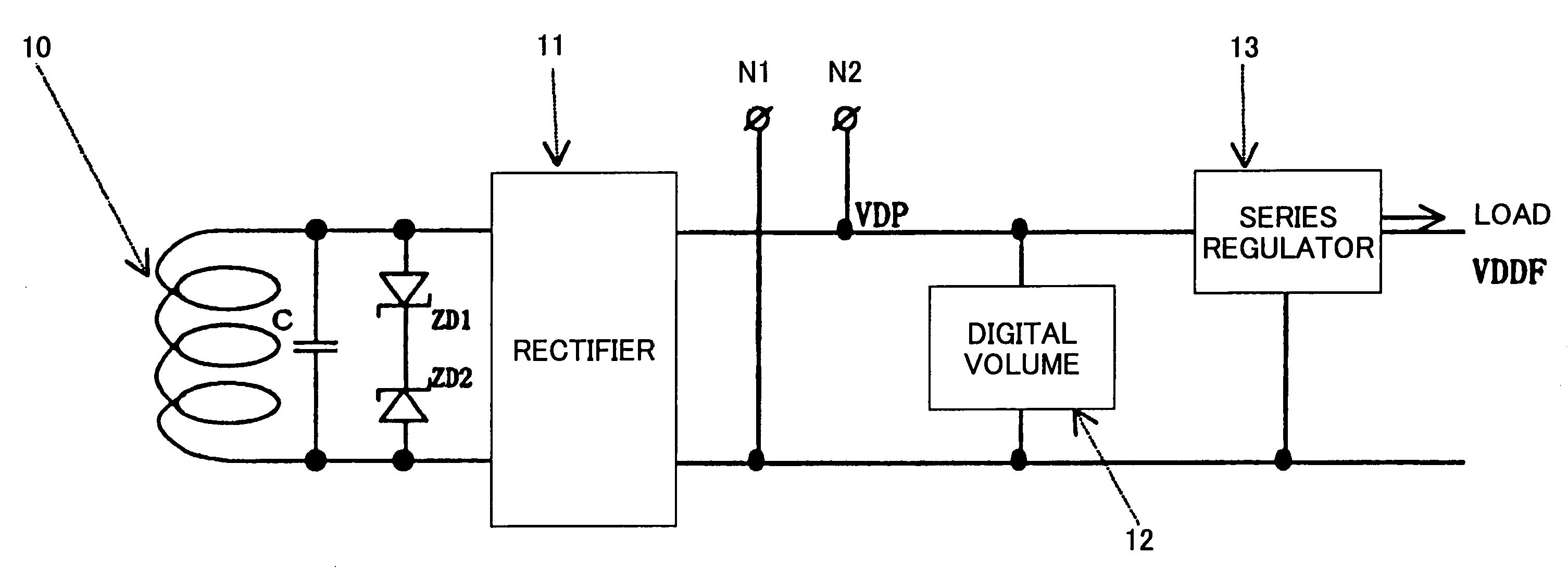
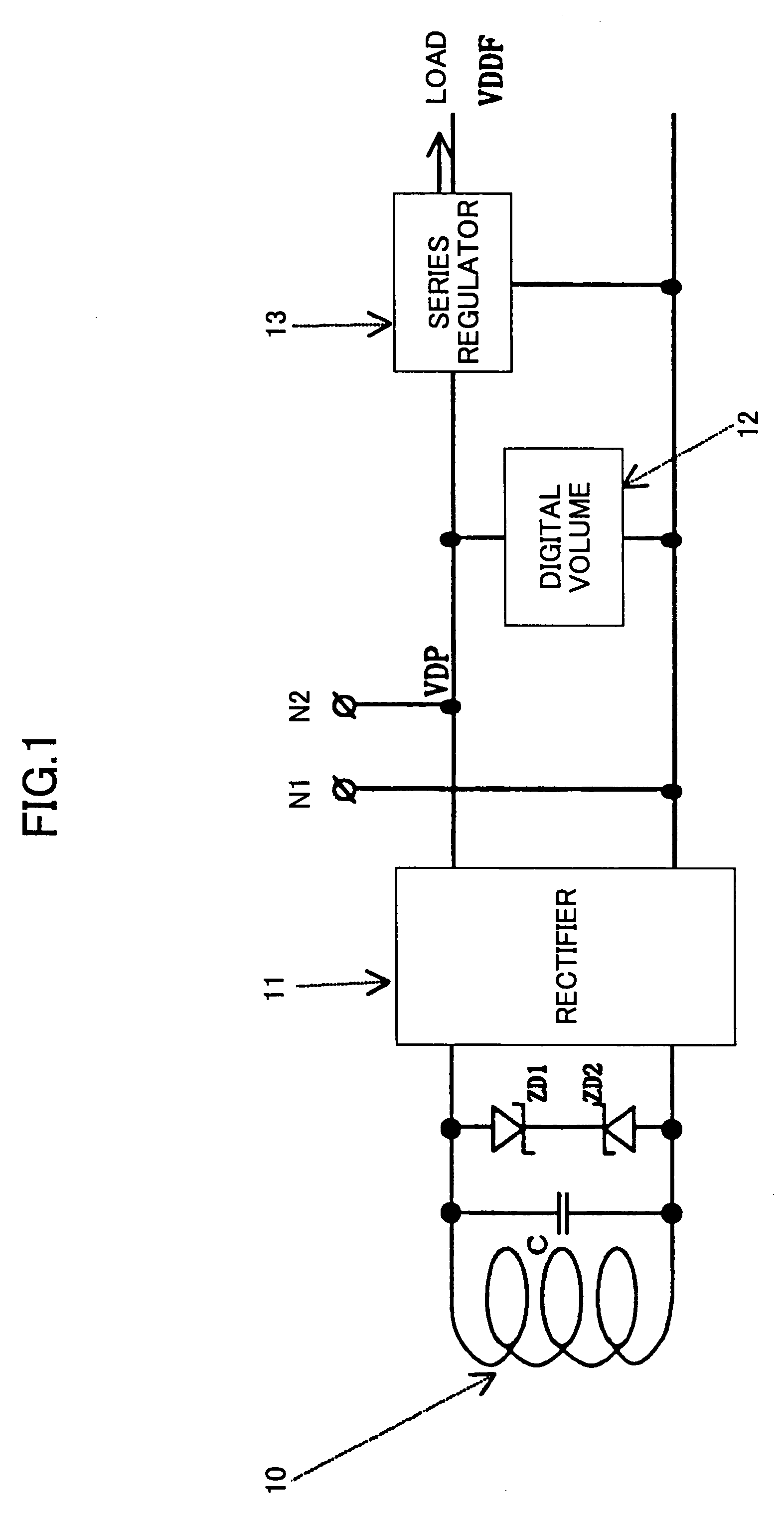
[0051]The power supply circuit of FIG. 3 includes the antenna 10, the rectifier 11, a voltage step-down circuit 41, and a shunt regulator 42. Although the capacitor C and the Zener diodes ZD1 and ZD2 for the resonance purpose are not illustrated in FIG. 3, these elements may as well be provided as in the construction of FIG. 1.

[0052]Electric power received at the antenna 10 is supplied to the rectifier 11 as an alternating voltage. The rectifier 11 converts the alternating voltage supplied from the antenna 10 into a direct-current voltage. The voltage step-down circuit 41 steps down the direct-current voltage supplied from the rectifier 11, thereby generating an output voltage VDDF. The shunt regulator 42 controls a shunt resistor provided between the output voltage V...

second embodiment

[0058]FIG. 5 is a block diagram showing the power supply circuit according to the invention. In FIG. 5, the same elements as those of FIG. 1 are referred to by the same numerals, and a description thereof will be omitted.

[0059]The power supply circuit of FIG. 5 includes the antenna 10, the rectifier 11, a current mirror circuit regulator 61, and a digital volume 62. Although the capacitor C and the Zener diodes ZD1 and ZD2 for the resonance purpose are not illustrated in FIG. 53, these elements may as well be provided as in the construction of FIG. 1.

[0060]Electric power received at the antenna 10 is supplied to the rectifier 11 as an alternating voltage. The rectifier 11 converts the alternating voltage supplied from the antenna 10 into a direct-current voltage. The current mirror circuit regulator 61 serves to supply a predetermined amount of an electric current to the load by utilizing the principle of a current mirror circuit. The digital volume 62 controls the amount of an elec...

third embodiment

[0072]FIG. 9 is a block diagram showing the power supply circuit according to the invention. In FIG. 9, the same elements as those of FIG. 1, FIG. 3, FIG. 5, and FIG. 7 are referred to by the same numerals, and a description thereof will be omitted.

[0073]The power supply circuit of FIG. 9 includes the antenna 10, the rectifier 11, the shunt regulator 42, the current mirror circuit regulator 61, and the digital volume 62 (or hardwired-set resistor 65). Although the capacitor C and the Zener diodes ZD1 and ZD2 for the resonance purpose are not illustrated in FIG. 9, these elements may as well be provided as in the construction of FIG. 1.

[0074]In the construction shown in FIG. 9, electric power received at the antenna 10 is supplied to the rectifier 11 as an alternating voltage. The rectifier 11 converts the alternating voltage supplied from the antenna 10 into a direct-current voltage. The current mirror circuit regulator 61 serves as a constant-current source and also as a voltage st...


PUM


Abstract

A power supply circuit for supplying power to a load includes an antenna which receives electric power, a rectifier coupled to the antenna and configured to convert an alternating voltage supplied from the antenna into a direct-current voltage, a voltage step-down circuit which steps down the direct-current voltage to generate an output voltage for provision to the load, a regulator which controls a resistance connected between the output voltage and a ground voltage in parallel with the load, thereby controlling a voltage level of the output voltage.

Description

CROSS-REFERENCE TO RELATED APPLICATIONS[0001]The present application is based upon and claims the benefit of priority from the prior Japanese Patent Application No. 2004-023982 filed on Jan. 30, 2004, with the Japanese Patent Office, the entire contents of which are incorporated herein by reference.BACKGROUND OF THE INVENTION[0002]1. Field of the Invention[0003]The present invention generally relates to regulator circuits, and particularly relates to a regulator circuit used in an IC (integrated-circuit) card.[0004]2. Description of the Related Art[0005]An IC card is used in various industrial fields where information and data inside the card need to be exchanged with external devices, and is exemplified by a commuter pass, a basic resident register, a credit card, etc. A system for exchanging data with external devices includes a system using noncontact-antenna-based communication and a system using contact-node-based communication. A system for supplying power to drive circuitry i...

Claims


Application Information

Patent Timeline
Patent Type & Authority Patents(United States)
IPC IPC(8): G05F1/00G05F1/56G05F1/613G05F3/26G06F1/26G06K7/00G06K19/07
CPCG06K7/0008G06K19/0701G06K19/0715G06K19/0723Y10S315/04G06K19/07G06F1/26
Inventor NAGASAWA, TAKAYUKIYAJIMA, SHINJITERAMOTO, TOSHIYUKIFUEKI, SHUNSUKEOKUBO, HIROSHIISOBE, MASAYOSHIKIKUCHI, TAKESHIRADECKI, ANDRZEJ
Owner FFC
Why Eureka
Try Eureka