Mixed 2D and 3D de-interlacer

a technology of interlacer and 2d, applied in the field of digital graphics systems, can solve the problems of introducing significant inaccuracies of certain image patterns, reducing the resolution of less detail in the final video display, so as to achieve maximum visual accuracy, enhance the effect of the effective resolution of the interpolation algorithm, and enhance the accuracy of the final output fram

Active Publication Date: 2006-11-28
ZHANGJIAGANG KANGDE XIN OPTRONICS MATERIAL
View PDF4 Cites 11 Cited by
  • Summary
  • Abstract
  • Description
  • Claims
  • Application Information

AI Technical Summary

Benefits of technology

[0018]To determine a luminance value for the blank pixel location, a weighted average is performed using pixel values from both the common-field and cross-field pixel pairs. The use of cross-field pixels by the invention increases the effective resolution of the interpolation algorithm, thereby enhancing the accuracy of the final output frame and avoiding the problems associated with conventional 2D de-interlacing techniques that only use common-field data. The actual weighting of the interpolation process is set by a predetermined weighting coefficient that controls the degree to which the cross-field pixel information is incorporated into the interpolation.
[0019]To provide maximum visual accuracy in the final video display, the mixed 2D-3D de-interlacing operation can also adjust the luminance values of pixels adjacent to the interpolated pixel. For example, according to an embodiment of the invention, the luminance of the top pixel in the common-field pixel pair can be adjusted towards the luminance value of its preceding pixel (i.e., the interpolated pixel in the same location as the top pixel but from the field immediately preceding the field of the top pixel). By adjusting the top pixel luminance in this manner, frame-to-frame variations can be further reduced to enhance the fidelity of the output video display.

Problems solved by technology

However, note that 2D de-interlacing necessarily reduces the resolution of the final video display, since only half of the image data (i.e., a single field) is used to generate each frame.
This not only results in less detail in the final video display, but also can introduce significant inaccuracies for certain image patterns.
Note, however, that the 3D de-interlacing methodology would lead to problems in a situation as described with respect to FIG. 2A, in which the rapid motion within a scene leads to view changes between successive fields.
Thus, because the interlacing process can generate the same sequence of fields from different original scenes, conventional 2D or 3D de-interlacing techniques will necessarily include one or the other of the display problems described above.

Method used


Image

  • Mixed 2D and 3D de-interlacer
  • Mixed 2D and 3D de-interlacer
  • Mixed 2D and 3D de-interlacer

Examples


Embodiment Construction

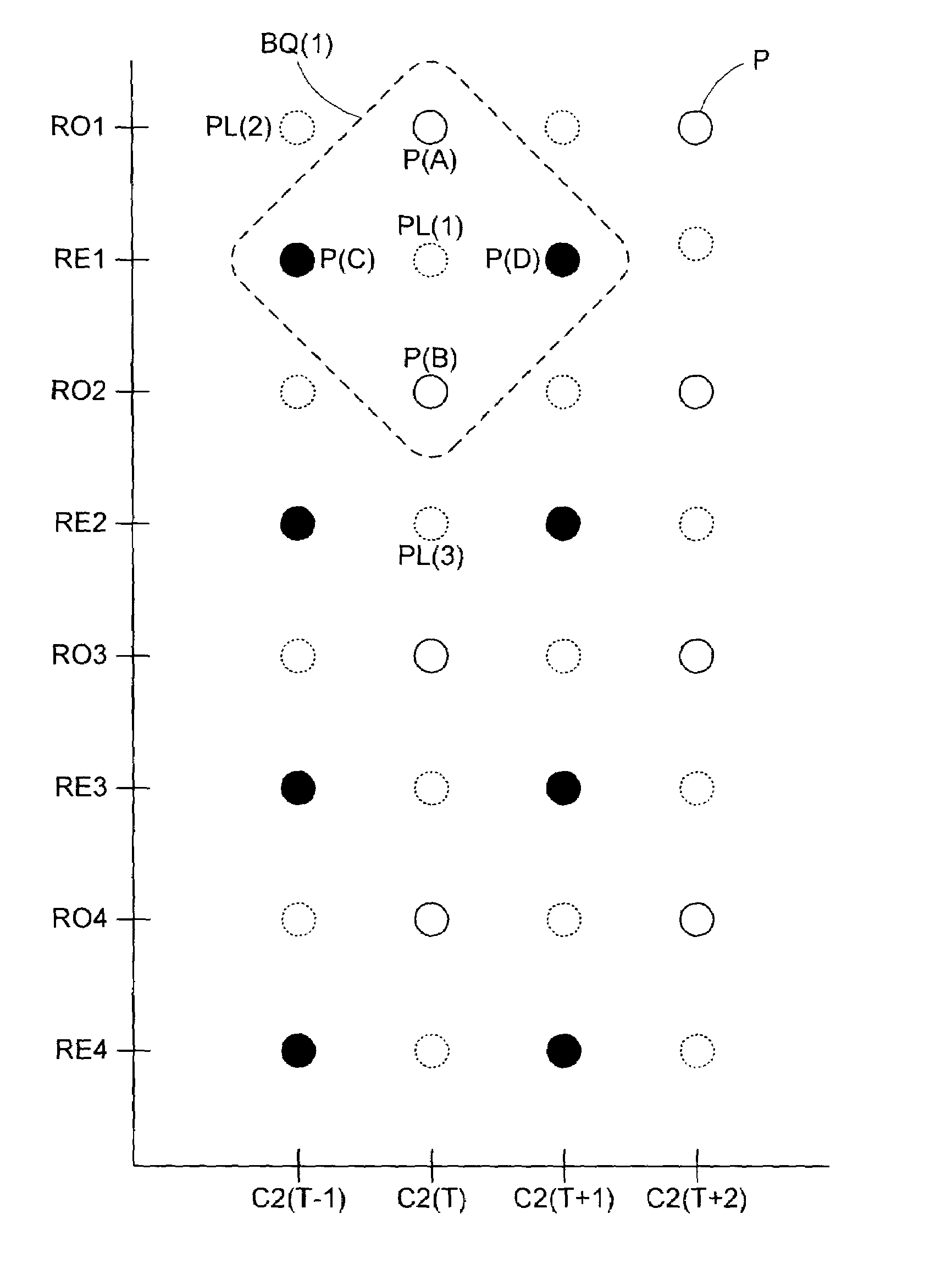
[0029]The invention provides a mixed 2D-3D de-interlacing methodology that allows interpolation to be used to generate an accurate video display from an interlaced video stream. Each field in the interlaced video stream is converted into a full frame by interpolating pixel data for each blank row in the field using both common-field pixel data (i.e., pixel data from the same field as the field being converted) and cross-field pixel data (i.e., pixel data from fields other than the field being converted). This “mixed” interpolation algorithm minimizes the resolution-based defects associated with conventional 2D de-interlacing of still images.

[0030]FIG. 3A shows four consecutive fields 600(T−1), 600(T), 600(T+1), and 600(T+2) of an interlaced video signal. Each of the fields includes twenty pixels P, arranged into five columns C1, C2, C3, C4, and C5 and four rows. Even fields 600(T−1) and 600(T+1) include even rows RE1, RE2, RE3, and RE4, while odd fields 600(T) and 600(T+2) include o...


PUM


Abstract

A de-interlacing methodology generates frames from interlaced video signals by incorporating data from multiple fields into an interpolation-based de-interlacing process. Pixels directly above and below a blank pixel location and pixels immediately before and after the blank pixel location (in the fields immediately preceding and following, respectively, the blank pixel field) can be used to interpolate a pixel value for the blank pixel location. The use of pixel data from multiple fields improves the resolution of the interpolation process, thereby improving output frame accuracy. Adjacent pixel values can also be adjusted to further improve the consistency of the visual display provided by the output frames.

Description

BACKGROUND OF THE INVENTION[0001]1. Field of the Invention[0002]The present invention relates to digital graphics systems. More specifically, the present invention relates to methods and circuits for accurately de-interlacing a video signal.[0003]2. Discussion of Related Art[0004]Modern video signals typically consist of a sequence of still images, or “frames.” By displaying the sequence of frames in rapid succession on a display unit such as a computer monitor or television, an illusion of full motion video can be produced. For example, a standard NTSC (National Television Systems Committee) television display has a frame rate of 29.970 fps (frames per second). For historical reasons, the frames in video displays for most consumer applications (and many professional applications) are formed from “interlaced” video signals in which the video signals are made up of “fields” that include half the data required for a full frame. Specifically, each field includes every other row of pixe...

Claims


Application Information

Patent Timeline
Patent Type & Authority Patents(United States)
IPC IPC(8): G09G5/00G06T3/40G09G3/20G09G5/14
CPCG06T3/4007G09G3/20G09G5/14G09G2310/0229G09G2320/02G09G2340/10
Inventor ZHU, GE
Owner ZHANGJIAGANG KANGDE XIN OPTRONICS MATERIAL
Why Eureka
Try Eureka