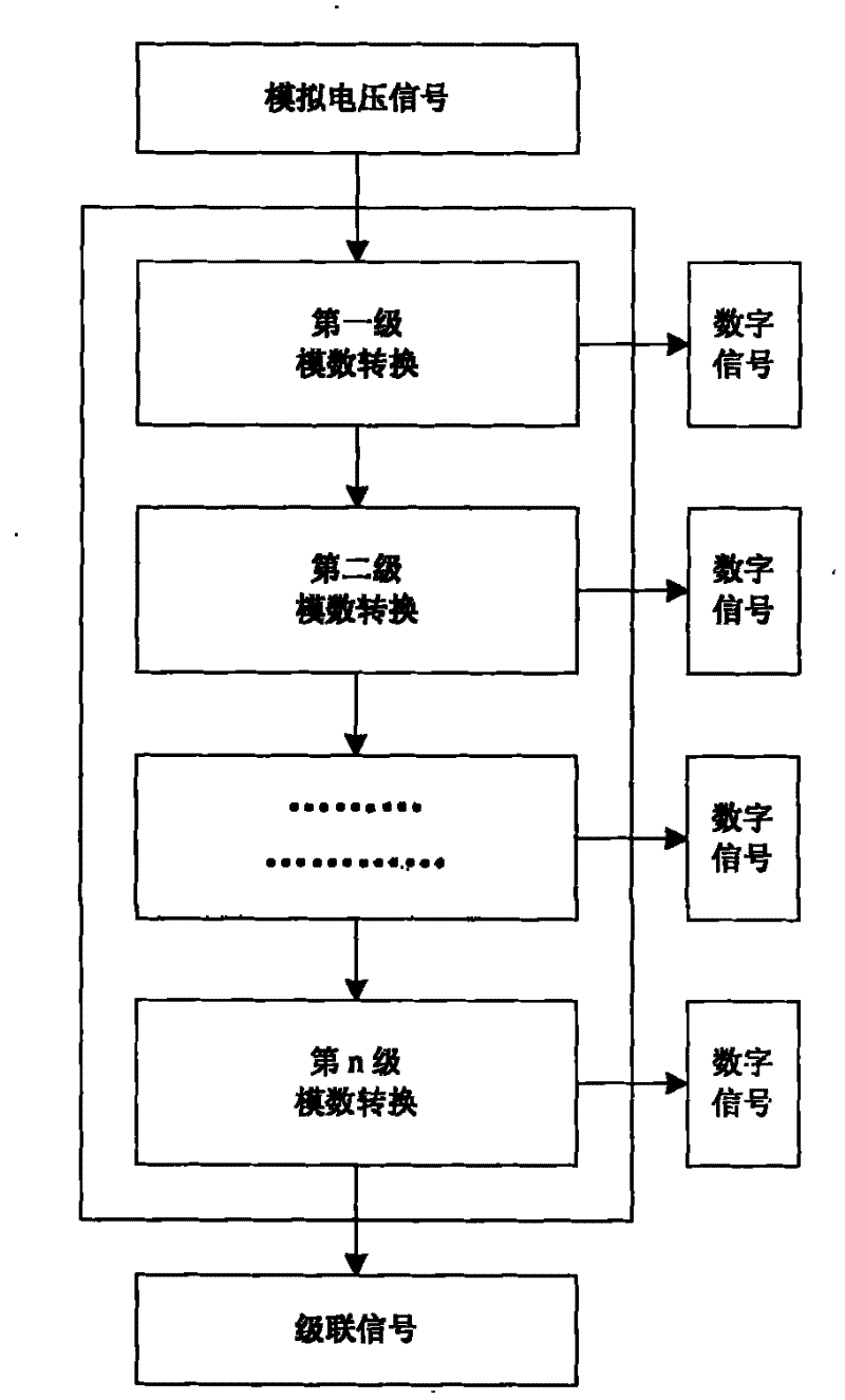
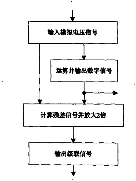
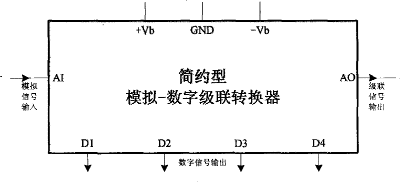
A/D direct computing conversion, A/D cascade converter and use thereof
A cascaded converter and analog-to-digital conversion technology, which is applied in the direction of analog-to-digital converter, analog/digital conversion, code conversion, etc., can solve the problems of high cost, low conversion rate, complex and large-scale circuits, etc.
- Summary
- Abstract
- Description
- Claims
- Application Information
AI Technical Summary
Problems solved by technology
Method used
Image
Examples
Embodiment 1
[0107]Dual Supply 16-Bit Economical Analog-to-Digital Converter
[0108] The schematic diagram of the dual power supply 16-bit economical analog-to-digital converter is as follows Figure 17 shown.
[0109] The dual-power 16-bit economical analog-to-digital converter consists of a sample-and-hold circuit S / H, four four-bit simple analog-to-digital cascade converters, two eight-bit latches, and two regulated power supplies.
[0110] Four four-bit simple A / D cascade converters are connected in cascade to form a cascade structure. The analog signal input terminal is connected to the output terminal of the sample and hold circuit S / H, and the sample and hold circuit S / H is connected to an external analog input. Signal.
[0111] The 16-bit digital signals output by four four-bit simple A / D cascade converters are respectively connected to the inputs of two eight-bit latches.
[0112] The two regulated power supplies output positive and negative power supply voltages respectively,...
Embodiment 2
[0116] Dual power supply 16-bit high-speed analog-to-digital converter
[0117] The schematic diagram of the dual power supply 16-bit high-speed analog-to-digital converter is as follows: Figure 18 shown.
[0118] The dual-power 16-bit high-speed analog-to-digital converter consists of a sample-and-hold circuit S / H, four four-bit high-speed analog-to-digital cascade converters, two eight-bit latches, and two dual-output regulated power supplies.
[0119] Four four-bit high-speed A / D cascade converters are connected in cascade to form a cascade structure. The analog signal input terminal is connected to the output terminal of the sample and hold circuit S / H, and the sample and hold circuit S / H is connected to an external analog input. Signal.
[0120] The 16-bit digital signals output by four four-bit high-speed A / D cascade converters are respectively connected to the inputs of two eight-bit latches.
[0121] The two regulated power supplies respectively output two groups o...
PUM
 Abstract
Description
Claims
Application Information
 - R&D
- Intellectual Property
- Life Sciences
- Materials
- Tech Scout
- Unparalleled Data Quality
- Higher Quality Content
- 60% Fewer Hallucinations
Browse by: Latest US Patents, China's latest patents, Technical Efficacy Thesaurus, Application Domain, Technology Topic, Popular Technical Reports.
© 2025 PatSnap. All rights reserved.Legal|Privacy policy|Modern Slavery Act Transparency Statement|Sitemap|About US| Contact US: help@patsnap.com


