Reinforced fiber panel and method of forming same

a technology of reinforced fiber and bending stiffness, which is applied in the field of three-dimensional structural products, can solve the problems of affecting the affecting the bending strength of the panel, so as to enhance the bending stiffness of the panel and enhance the bending stiffness. the effect of the panel and the structure is not affected by moisture, and the quality of the wood adds to the cost of the pall

Inactive Publication Date: 2006-12-05
SONOCO DEV INC
View PDF21 Cites 29 Cited by
  • Summary
  • Abstract
  • Description
  • Claims
  • Application Information

AI Technical Summary

Benefits of technology

[0006]These and other needs are provided by the present invention that describes a reinforced product, such as a pallet, made from panels comprising fibrous materials, such as paperboard. Advantageously, the panel is structurally reinforced for greater strength by providing a channel and reinforcing member along at least a portion thereof. The reinforcing member is fitted into the channel and bonded therein to enhance the bending stiffness of the panel. The reinforcing member preferably comprises a paperboard lamination formed from multiple plies of paperboard or papermaking fibers adhered together and then folded to form the desired cross-sectional shape. The plies of the reinforcing member preferably are dry-bonded to each other using an adhesive, such as a modified silicate adhesive. Such a dry-bonding process adds little or no moisture to the structure. In one aspect of the invention, the panel is reinforced by being bonded to another panel, which may or may not have a reinforcing member of its own.
[0008]A reinforcing member is positioned in the channel and bonded thereto for increasing the bending resistance of the panel. The reinforcing member can be of various shapes and sizes, including polygonal, circular, oval, and elliptical. In addition, the reinforcing member can have a cross-sectional shape, such as T-shaped, I-shaped, V-shaped, |-shaped and L-shaped. In one embodiment, the reinforcing member has a top end that is flush with the distal ends of the ribs, but in another embodiment the reinforcing member extends beyond the distal ends of the ribs.
[0010]In yet another embodiment, the face sheet is arranged such that the exterior side of the face sheet defines a channel, such as by folding one end of the panel on itself to form the channel. A reinforcing member is positioned in the channel in order to increase the bending resistance of the panel. In one such arrangement, the panel includes two face sheets, each having a plurality of integral and intersecting ribs, and wherein the face sheets are arranged so that the ribs of each face sheet are proximate the ribs of the other sheet. In all of the above embodiments, the panel is of superior strength and durability, which improves the lifespan and reduces costs of operation.
[0011]Methods are also provided by the present invention. In particular, one method of the present invention includes forming a reinforced panel for supporting objects including the steps of forming a first face sheet having a plurality of integral ribs extending therefrom, whereby the ribs have distal ends and form contiguous cells. A first channel is formed in the first face sheet that extends across a plurality of the contiguous cells, and a first reinforcing member is secured in the first channel for increasing the bending resistance of the panel. In one embodiment, the channel forming step and the face sheet forming step occur concurrently, such as by pressing and heating a slurry of paperboard material in a mold so that the channel is formed during the creation of the face sheet. Alternatively, the channel may be cut into the first face sheet after the face sheet has been formed. The first reinforcing member may be secured in the channel such that the reinforcing member is flush with the distal ends of the integral ribs, although it is possible that the reinforcing member may be secured in the channel so that a portion of the reinforcing member extends beyond the distal ends of the integral ribs. In another embodiment, the method further includes forming a second face sheet having a plurality of integral ribs, and forming a second channel that extends across a plurality of the cells defined by the ribs. A second reinforcing member may also be provided, and the second reinforcing member, the first reinforcing member, or both, are attached to the second channel. The first face sheet and the second face sheet are also attached to one another in order to provide a panel having increased bending resistance.
[0012]Accordingly, the panel and methods of forming a panel according to the present invention provide a structure having superior bending resistance over conventional paperboard or wood based structures. In addition, the panel of the present invention overcomes the disadvantages of wood plank and plastic panels and the like. Advantageously, the structures and methods afforded by the present invention are low cost, highly efficient, and safe.

Problems solved by technology

Not only does obtaining quality wood add to the cost of the pallet, a significant portion of the supply trees are wasted during production.
The nailed joints may be sturdy at first, but they tend to fail due to the rigors of transporting goods.
In fact, normal use typically destroys most pallets after an alarmingly low number of uses, as weather, product weight, and mishandling all play a role in their demise.
Instead of repairing broken pallets, however, most users simply throw the pallets away, which creates further waste and increases the costs of transporting goods.
Molded plastic panels are also disadvantageous, in that they are constructed of non-natural materials that do not break down after the panels have been discarded.
Plastic panels also tend to have low bending resistance, which limits the applications suitable for plastic panels.
Unfortunately, the inventors of the present invention have discovered that panels created by the teachings of Setterholm and / or similar techniques are susceptible to significant deformation when placed under load.
This deformation can lead to immediate failure of the panel or greatly reduce the fatigue lifespan of the panel.

Method used


Image

  • Reinforced fiber panel and method of forming same
  • Reinforced fiber panel and method of forming same
  • Reinforced fiber panel and method of forming same

Examples


Embodiment Construction

[0023]The present inventions now will be described more fully hereinafter with reference to the accompanying drawings, in which some, but not all embodiments of the invention are shown. Indeed, these inventions may be embodied in many different forms and should not be construed as limited to the embodiments set forth herein; rather, these embodiments are provided so that this disclosure will satisfy applicable legal requirements. Like numbers refer to like elements throughout.

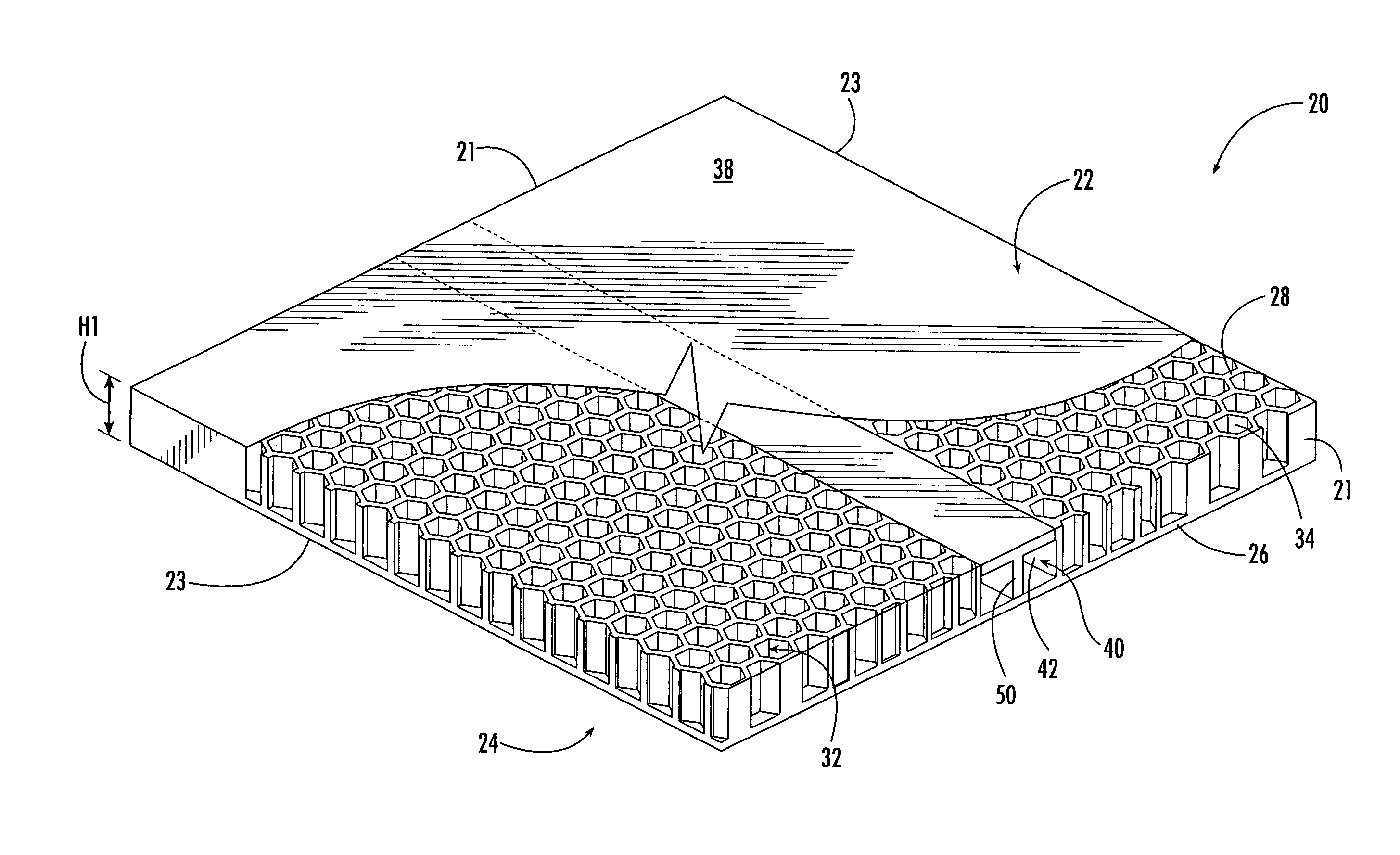
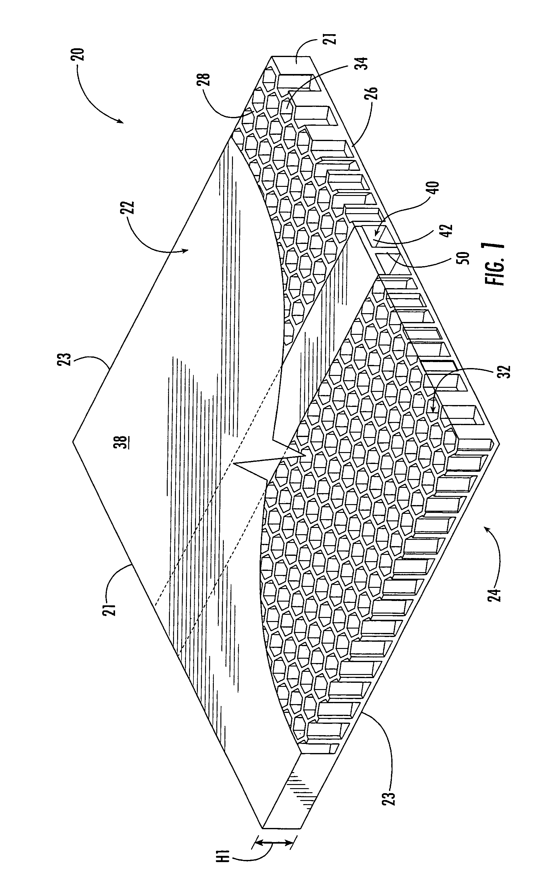
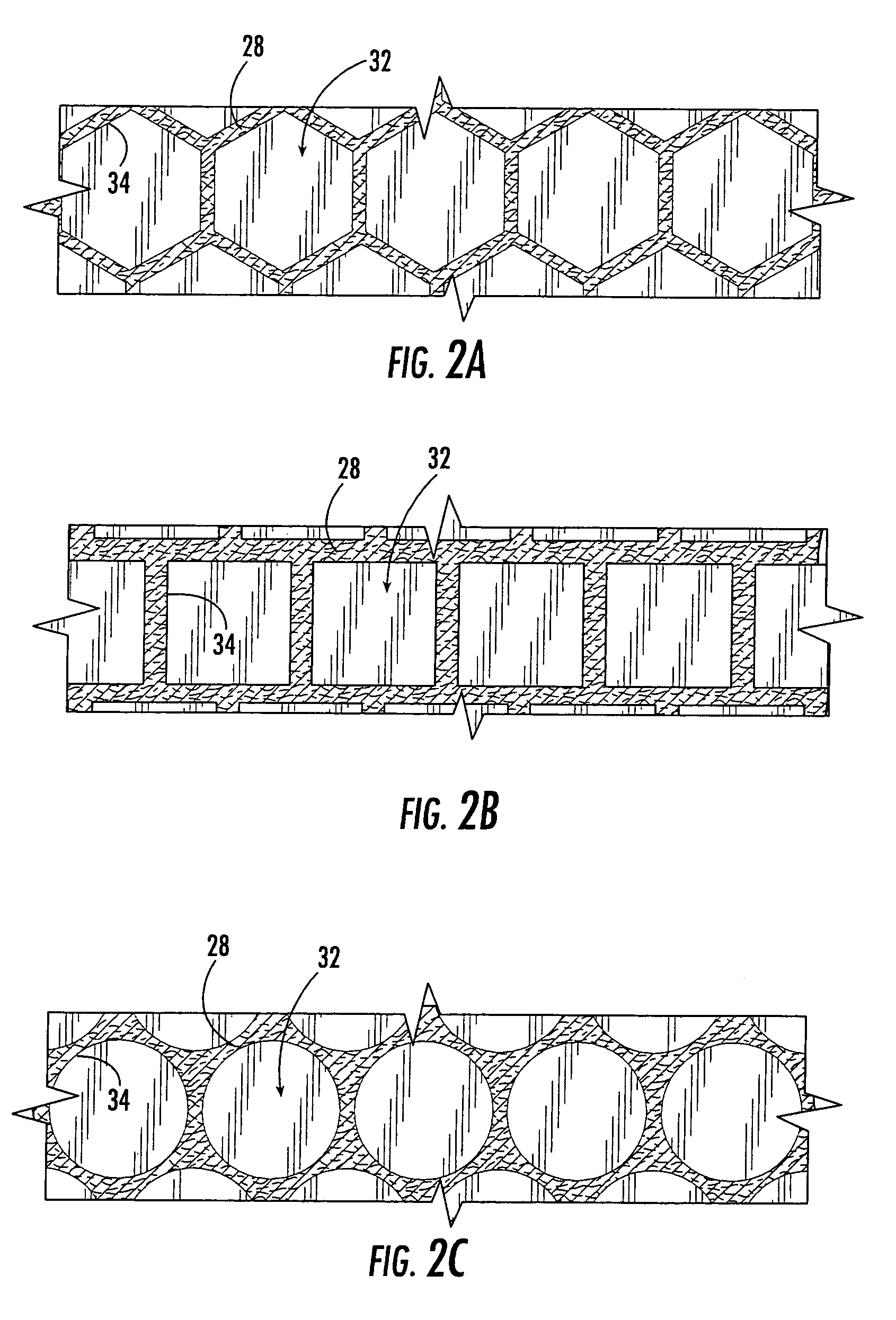
[0024]Turning now to the figures, FIGS. 1 and 2 show a reinforced support structure or panel 20 according to one embodiment of the present invention. The panel 20 is useful for supporting objects and transporting goods, although other uses and benefits are contemplated by the present invention. As shown, the panel 20 has opposing ends 21 and sidewalls 23. The thickness of the panel 20 is defined as H1, and is determined by the distance between a top or interior side 22 and a bottom or exterior side 24 of a face...


PUM


Abstract

The present invention is directed to a reinforced panel that includes a face sheet having an interior side and an exterior side, a plurality of integral and intersecting ribs having distal ends and projecting from the interior side of the face sheet to form contiguous cells, and a reinforcing member positioned in a channel and secured thereto for increasing bending resistance of the panel.

Description

BACKGROUND OF THE INVENTION[0001]The present invention relates to three-dimensional structural products, and more particularly to structural products made from wood products and methods of forming same.[0002]Structural panels can be used in a variety of applications, including applications similar to those in which plywood or lumber conventionally are used. For instance, structural panels can be used in the construction of pallets. Pallets and similar support devices are common articles that are used to transport goods in a variety of industries. Pallets can come in many shapes and sizes, and are typically formed from wood planks or molded plastic. While these types of pallets are commonplace, they suffer from several disadvantages. First, pallets formed from wood planks require first quality pieces that are free from serious defects that could compromise the integrity of the pallet. Not only does obtaining quality wood add to the cost of the pallet, a significant portion of the sup...

Claims


Application Information

Patent Timeline
Patent Type & Authority Patents(United States)
IPC IPC(8): E04C2/32E04C2/54E04C2/16E04C2/36
CPCE04C2/16E04C2/365
Inventor RENCK, LAWRENCE E.
Owner SONOCO DEV INC
Why Eureka
Try Eureka