Gas turbine combustor, combustion method of the gas turbine combustor, and method of remodeling a gas turbine combustor

a gas turbine and combustor technology, applied in the ignition of turbine/propulsion engines, engine starters, lighting and heating apparatus, etc., can solve the problems of reducing cooling performance, self-ignition of air fuel mixture, and caulking phenomenon, and achieve excellent nox reduction

Inactive Publication Date: 2006-12-05
MITSUBISHI HITACHIPOWER SYST LTD
View PDF19 Cites 73 Cited by
  • Summary
  • Abstract
  • Description
  • Claims
  • Application Information

AI Technical Summary

Benefits of technology

[0010]Accordingly, an object of the present invention is to provide a gas turbine combustor that makes adequate combustion with a combustor for which gas fuel and liquid fuel can be used, and that is excellent in minimizing NOx, a combustion method of the gas turbine combustor, and a method of remodeling a gas turbine combustor.

Problems solved by technology

The stuck fuel is carbonated, and this is likely to cause a caulking phenomenon.
This poses problems that self-ignition of air fuel mixture due to the char and flashback caused by flame flowing into the premixed combustion burner occur.
There arise other problems that cooling performance is lowered at the char stuck portion of a structure and peeling-off chars collide against another structure to damage it.
Further, the system has to be complicated because pre-evaporation premixed system is used together with the diffusion combustion system, which requires a means of preventing caulking in the fuel nozzle and maintenance work.
With the technique described in Patent Document 2, the same problems as described above occur even when the pre-evaporation premixed combustion system uses liquid fuel.
This poses a problem that the diffusion flame cannot reach the cross-fire tube connected to the side wall of the combustor, which makes it impossible to ignite the adjacent combustor.
Further, when pre-evaporation mixing is made using liquid fuel, pre-evaporation cannot be made because air temperature at the time of ignition is too low.
This requires use of a pilot burner, and the above-described problem with flame transmission becomes more significant.

Method used


Image

  • Gas turbine combustor, combustion method of the gas turbine combustor, and method of remodeling a gas turbine combustor
  • Gas turbine combustor, combustion method of the gas turbine combustor, and method of remodeling a gas turbine combustor
  • Gas turbine combustor, combustion method of the gas turbine combustor, and method of remodeling a gas turbine combustor

Examples


Embodiment Construction

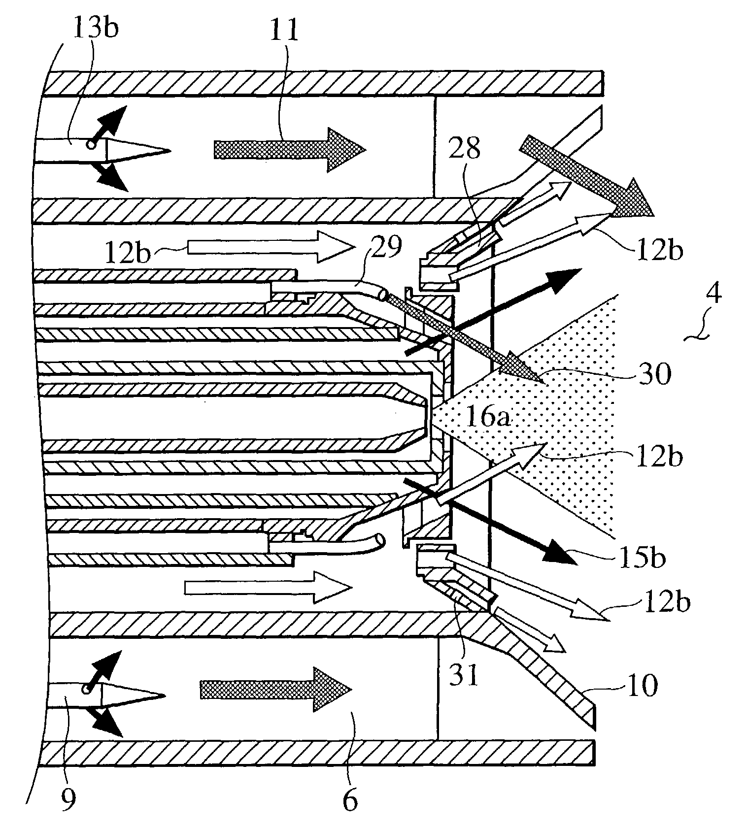
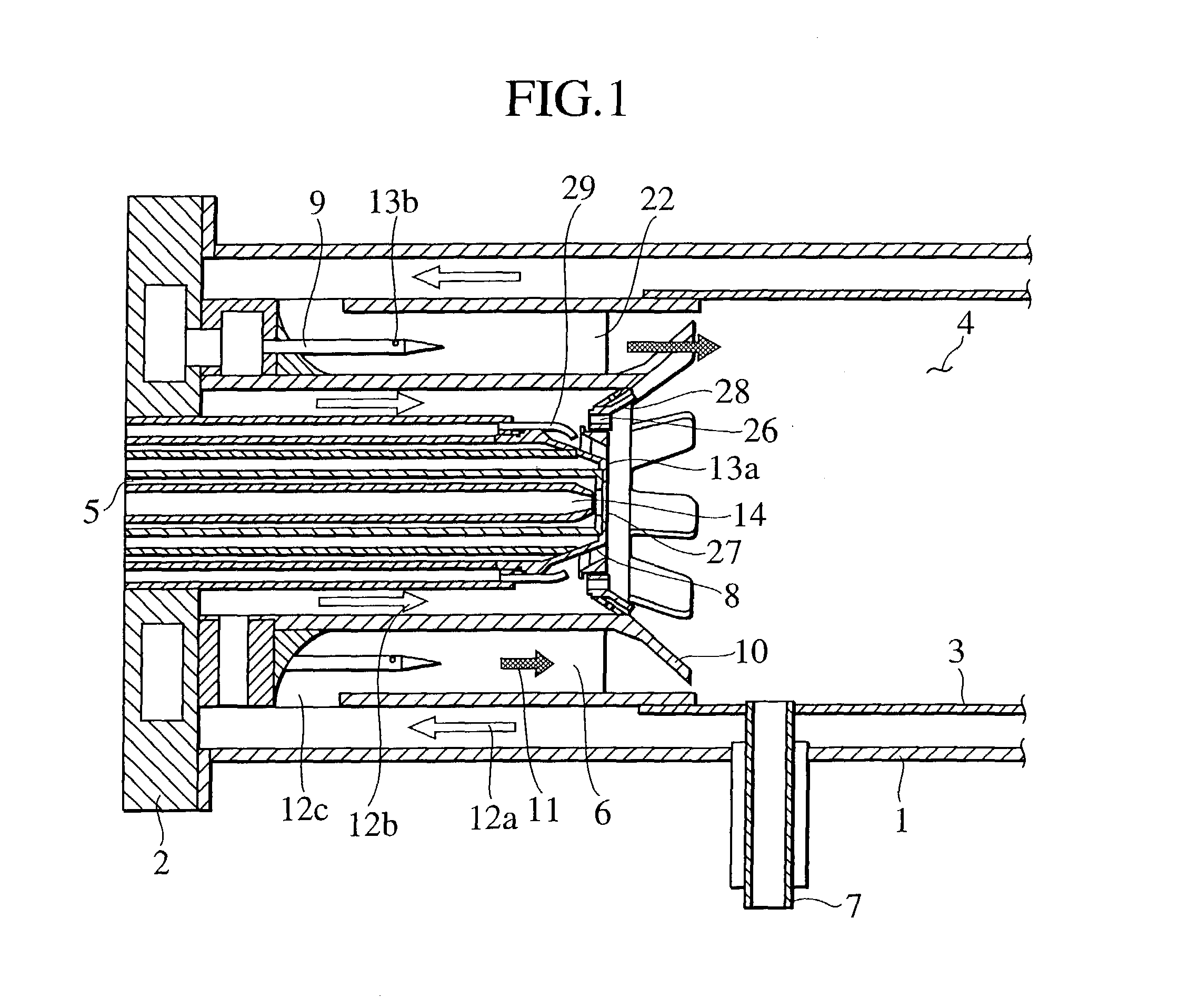
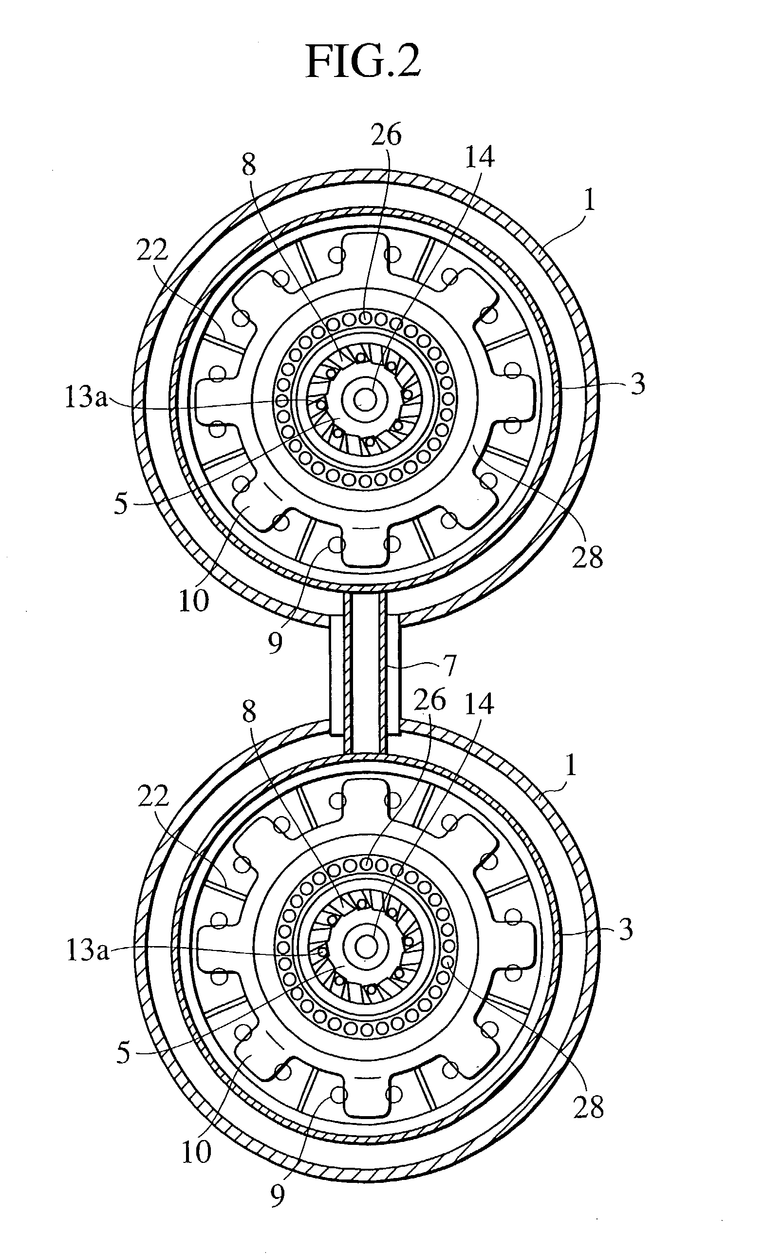
[0029]A gas turbine combustor comprises a pilot burner, a premixed combustion burner disposed on the outer circumference of the pilot burner, and a combustor liner in an approximately cylindrical shape which is disposed on the downstream side of the premixed combustion burner, and which defines a combustion chamber in the inner wall. In addition, the gas turbine combustor comprises flame stabilizers radially disposed at the exit of the premixed combustion burner, and a plurality of air nozzles located inside the premixed combustion burner, which spout out air into the combustion chamber. The pilot burner is provided with a fuel injection means which injects at least one of gas fuel and liquid fuel. Since flame stabilizers are radially disposed at the exit of the premixing burner, fuel of the pilot burner forms flame on the flame stabilizing surface. When gas fuel is used, premixed flame is stabilized, and when liquid fuel is used, mixing of air ejected from the premixed combustion b...


PUM


Abstract

A gas turbine combustor comprises a premixed combustion burner disposed on the periphery of a pilot burner, an approximately cylindrical combustor liner disposed on the downstream side of the premixed combustion burner, which defines a combustion chamber in the liner. The gas turbine combustor is characterized by further comprising flame stabilizers radially disposed at the exit of the premixed combustion burner, and a fuel injection means with which the pilot burner is provided injects at least one of gas fuel and liquid fuel, in which a plurality of air nozzles are provided which are located outside the pilot burner and inside the premixed combustion burner, and which spout out air into the combustion chamber. Adequate combustion can be accomplished with a combustor which is capable of using gas fuel and liquid fuel, and at the same time, NOx can be reduced.

Description

BACKGROUND OF THE INVENTION[0001]The present invention relates to a gas turbine combustor, a combustion method of the gas turbine combustor and a method of remodeling a gas turbine combustor.[0002]Examples of conventional gas turbine combustors using both a premixed combustion method and a diffusion combustion method are disclosed by Patent Documents 1 and 2, etc.[0003][Patent Document 1][0004]Japanese Patent Laid-open No. 11-94255[0005][Patent Document 2][0006]Japanese Patent Laid-open No. 3-255815[0007]With the technique described in Patent Document 1, liquid fuel not evaporated completely and remained in the evaporating process after injection sticks to the flame stabilizers as it is. The stuck fuel is carbonated, and this is likely to cause a caulking phenomenon. This poses problems that self-ignition of air fuel mixture due to the char and flashback caused by flame flowing into the premixed combustion burner occur. There arise other problems that cooling performance is lowered ...

Claims


Application Information

Patent Timeline
Patent Type & Authority Patents(United States)
IPC IPC(8): F02C3/00F23R3/18F23R3/28F23R3/34F23R3/36
CPCF23R3/18F23R3/286F23R3/343F23R3/36
Inventor HAYASHI, AKINORIINAGE, SHINICHIKOIZUMI, HIROMITAKEHARA, ISAOITO, KAZUYUKISASAO, TOSHIFUMIMURATA, HIDETARO
Owner MITSUBISHI HITACHIPOWER SYST LTD
Why Eureka
Try Eureka