Solder assistor

Inactive Publication Date: 2006-12-05
MEADE JOHN
View PDF5 Cites 22 Cited by
  • Summary
  • Abstract
  • Description
  • Claims
  • Application Information

AI Technical Summary

Benefits of technology

[0009]It is still a further object of the present invention to provide a device which allows for solder to be applied to the complete distal end of the bar portion of wires.
[0010]It is still a further object of the present invention to provide a device which allows for the removal of excess solder.
[0011]The device of the present invention is useful for securing and positioning at least two wires together such that the wires can be electrically connected. The device is comprised of clamps attached to a planar surface. Each of these clamps can be used to secure and position a wire such that all of the wires desired to be electrically connected are adjacent to each other and, in the case of two wires, retain the same linear disposition of the remainder of the wire. This allows for the user of the device to easily and efficiently electrically connect the wire

Problems solved by technology

This can be a difficult task as the art of soldering requires that the person soldering use both hands to complete the task.
Previous attempts to resolve the positioning and securing problem have not been adequate.
This process only allowed for the soldering of the remaining exposed wire.
First, because the clamp was attached at the ends of the exposed wire, those portions of the wire could not be soldered.
This results in an inefficient use of space in what can be extremely confined circumstances (such

Method used


Image

  • Solder assistor
  • Solder assistor
  • Solder assistor

Examples


Embodiment Construction

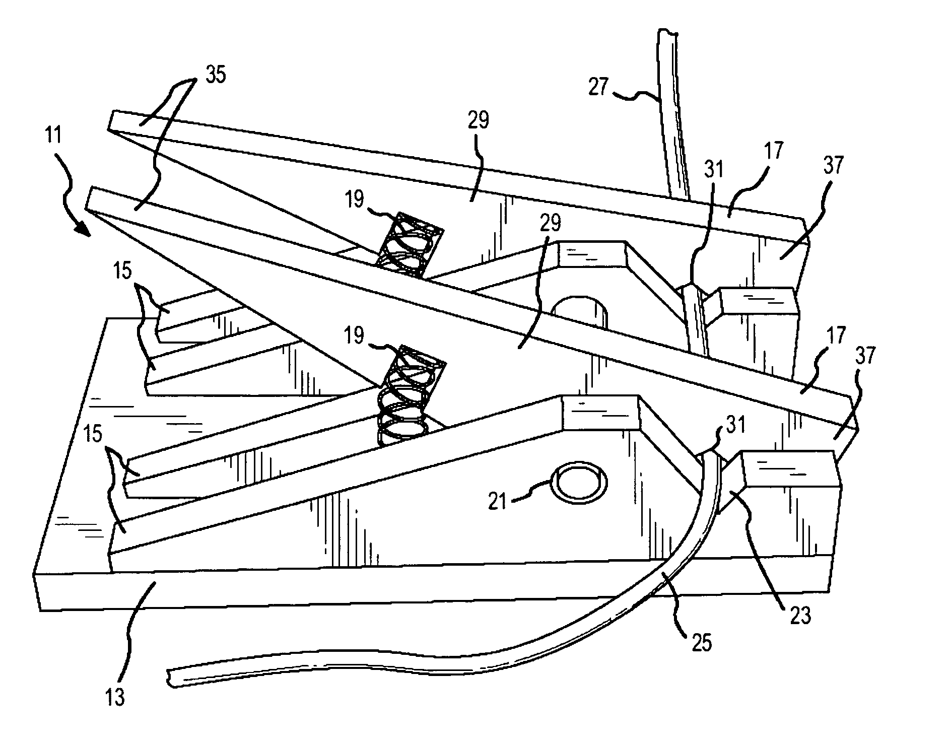
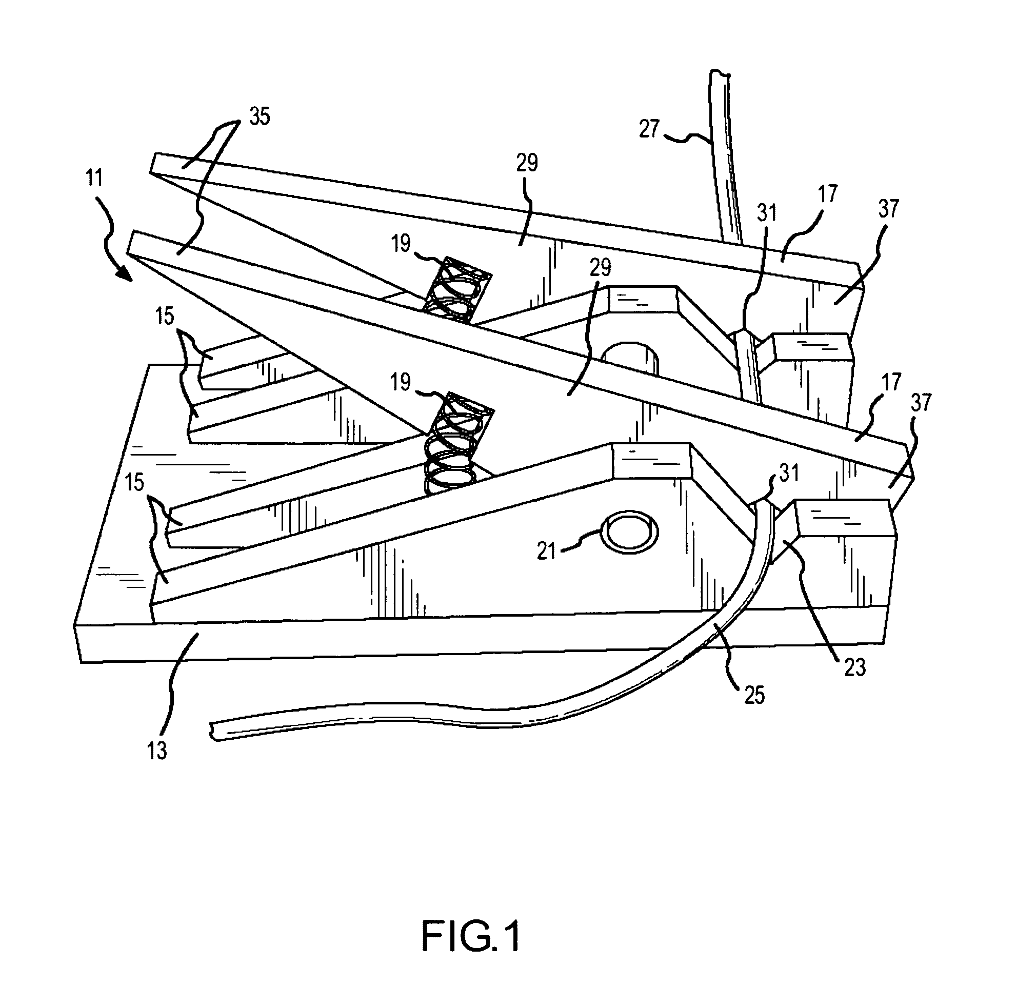
[0016]With reference to FIG. 1, in one embodiment, device 11 is comprised of generally planar base section 13, receiving guides 15, securing means 17, springs 19 and fulcrum 21. Receiving guides 15, which are to be provided in matched pairs, are further comprised of trough 23 which will receive and position electrically conductive material 25. Electrically conductive material 25 can be a wire, but more generally, can be any generally cylindrical material for which a soldering process is to be applied. For ease of identification, electrically conductive material 25 will hereafter be referred to as wire 25. Once properly positioned in trough 23, wire 25 will be secured by wire securement mechanism 17 using the force applied by spring 19 transferred about fulcrum 21. Spring 19 must have a k-value which will be sufficient to secure wire 25 while not deforming wire 25 such that the exposed wire portions (shown with reference to FIG. 3) will retain the generally linear form of the wire 25...


PUM

PropertyMeasurementUnit
Electrical conductivityaaaaaaaaaa
Electrical resistanceaaaaaaaaaa
Areaaaaaaaaaaa

Abstract

The device of the present invention is useful for facilitating the soldering of materials. More specifically, the device of the present invention is useful for the positioning and securing of at least two electrically conductive materials such that those materials can be effectively soldered together.

Description

FIELD OF THE INVENTION[0001]The present invention relates to the field of devices used to facilitate the electrical connection of at least two electrically conductive materials. More specifically, the present invention relates to the field of soldering devices.BACKGROUND OF THE INVENTION[0002]In many fields, including but not limited to the fields of general automotive electronics and audio / video electronics, it is often necessary to electrically connect at least two different wires. This connection is often achieved through the use of solder. The art of soldering requires the melting of a metallic alloy to unite at least two other metallic surfaces. In the relevant fields, solder is used to electrically connect at least two separate wires to unite those wires and facilitate the passage of electricity through those wires.[0003]The strength of a solder connection depends on the environment in which the soldering process is conducted. It is necessary to ensure ample contact between th...

Claims


Application Information

Patent Timeline
IPC IPC(8): B25B1/20
CPCB23K3/08B23K3/087Y10T29/53961
Inventor MEADE, JOHN
Owner MEADE JOHN
Why Eureka
Try Eureka