
Apparatus for reducing effort of clutch pedal for vehicle

a technology of clutch pedal and pedal, which is applied in the direction of mechanical control devices, instruments, process and machine control, etc., can solve the problems of easy breakage of parts including the spring bush connecting the turnover spring and the pedal member, the fatigue of the driver when operating the clutch pedal is relatively increased, and the like. , to achieve the effect of reducing the effort felt, reducing the effort needed for the operation of the clutch pedal, and reducing the effort of the par

Inactive Publication Date: 2016-05-03
HYUNDAI MOTOR CO LTD +1
View PDF15 Cites 0 Cited by
  • Summary
  • Abstract
  • Description
  • Claims
  • Application Information

AI Technical Summary

Benefits of technology

The present invention is an apparatus for reducing the effort needed to operate a clutch pedal in a vehicle. It includes a hinge pipe, a spring housing, and a leaf spring that all work together to provide a more flexible and comfortable experience for the driver. The apparatus can be used in high-output vehicles without causing damage. Its technical effect is to reduce the effort required to operate the clutch pedal of a vehicle, making it more comfortable and efficient for drivers.

Problems solved by technology

However, when the spring force of the turnover spring is increased, an effort applied to a clutch pedal is increased, and as a result, fatigue of a driver when operating the pedal is relatively increased, and in particular, when the diameter of a turnover spring is increased, a concentrative load applied to the turnover spring is increased, parts including a spring bush connecting the turnover spring and a pedal member, and the like are easily broken.

Method used


Image

  • Apparatus for reducing effort of clutch pedal for vehicle
  • Apparatus for reducing effort of clutch pedal for vehicle
  • Apparatus for reducing effort of clutch pedal for vehicle

Examples


Embodiment Construction

[0029]Reference will now be made in detail to various embodiments of the present invention(s), examples of which are illustrated in the accompanying drawings and described below. While the invention(s) will be described in conjunction with exemplary embodiments, it will be understood that present description is not intended to limit the invention(s) to those exemplary embodiments. On the contrary, the invention(s) is / are intended to cover not only the exemplary embodiments, but also various alternatives, modifications, equivalents and other embodiments, which may be included within the spirit and scope of the invention as defined by the appended claims.

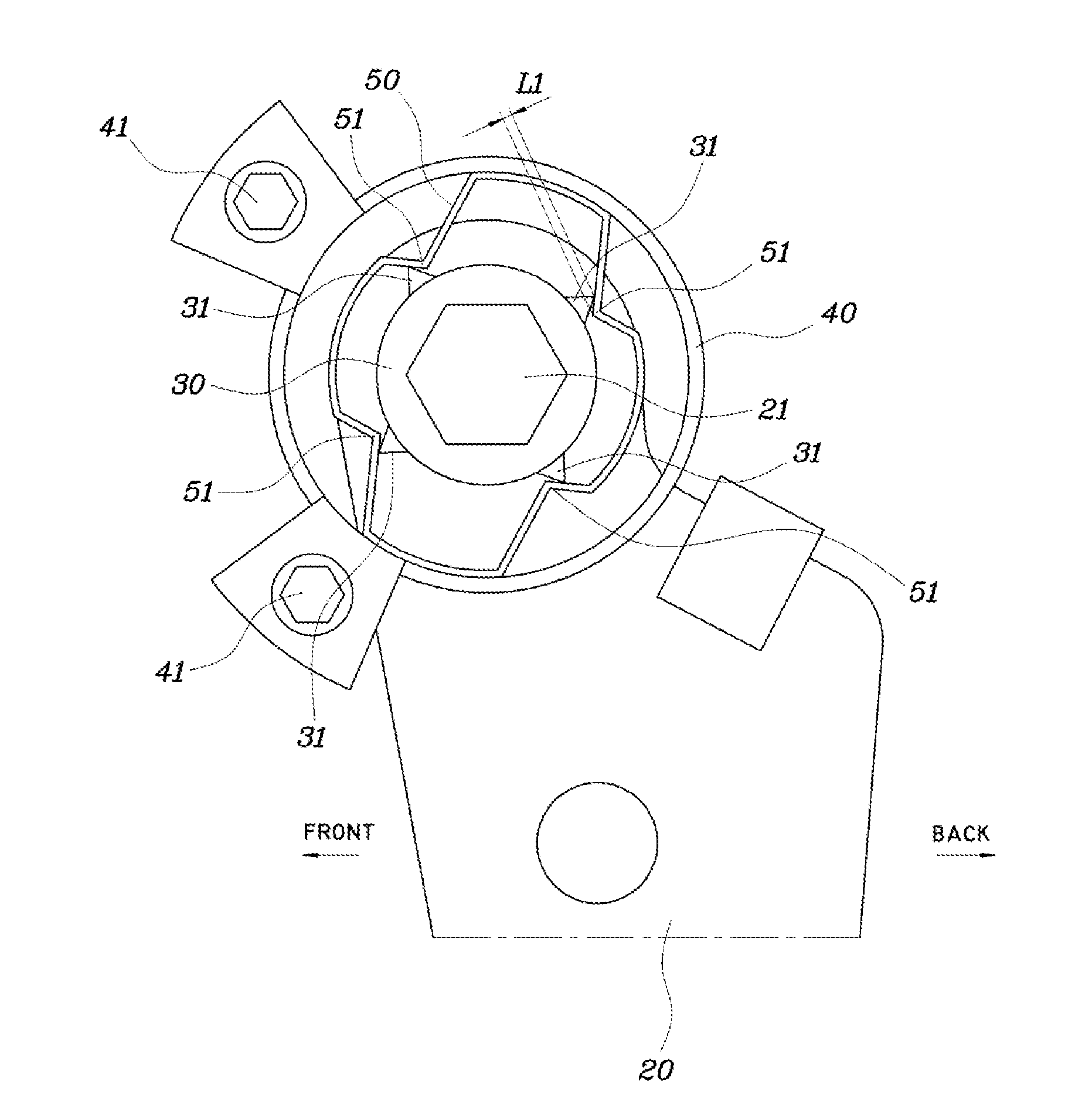
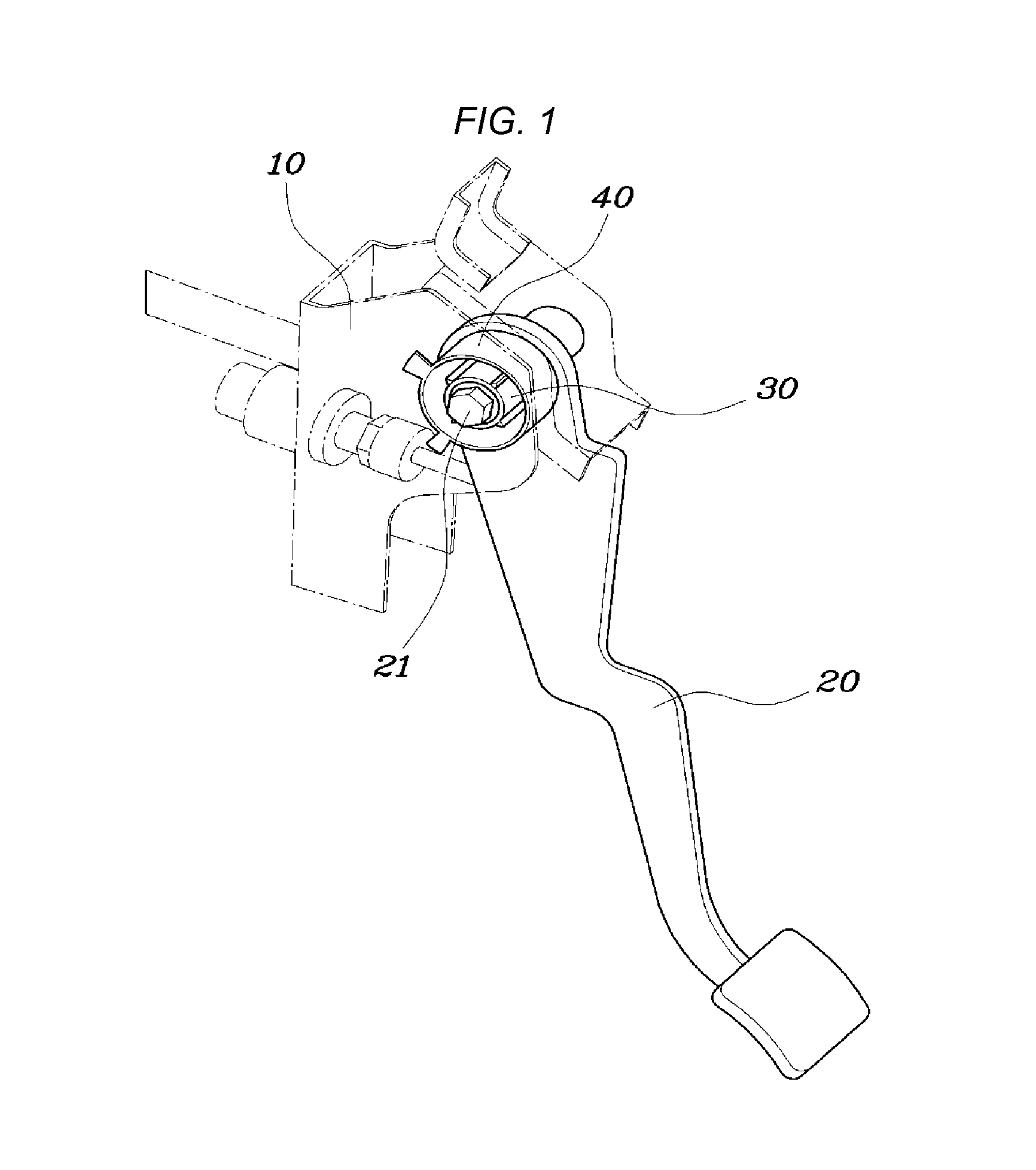
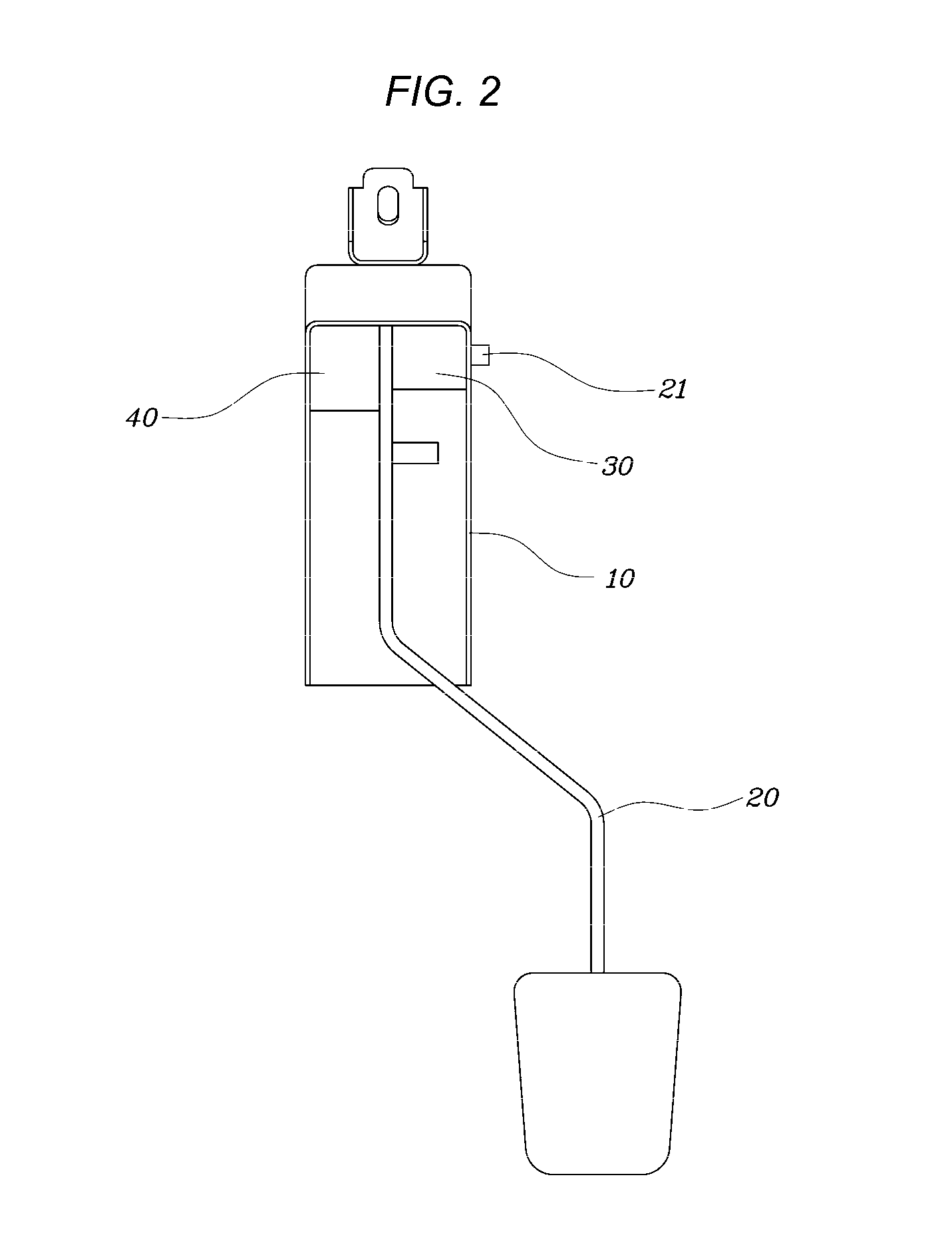
[0030]The apparatus for reducing an effort of a clutch pedal for a vehicle according to the present invention is configured to include a pedal member 10 fixedly installed in a front chassis panel (dash panel) adjacent the lower part of a driver seat; a pedal arm 20 installed in the pedal member 10 with an upper portion to be rotatable...


PUM


Abstract

An apparatus for reducing an effort of a clutch pedal for a vehicle may include a hinge pipe provided in an upper portion of a pedal arm so that a pedal hinge penetrates the hinge pipe and having a plurality of pipe protrusions which protrude in a radial direction along a circumferential direction of the hinge pipe on an outer peripheral surface of the hinge pipe, a spring housing fixedly installed on an inside of a pedal member facing the hinge pipe, and a leaf spring positioned in an inner space of the spring housing and fixedly installed in the spring housing to be flexibly bent and having a curve portion contacting one or each of the pipe protrusions.

Description

CROSS-REFERENCE TO RELATED APPLICATION[0001]The present application claims priority of Korean Patent Application Number 10-2013-0149377 filed on Dec. 3, 2013, the entire contents of which application are incorporated herein for all purposes by this reference.BACKGROUND OF INVENTION[0002]1. Field of Invention[0003]The present invention relates to an apparatus for reducing the effort of a clutch pedal for a vehicle, and more particularly, to a technology associated with an apparatus for reducing the effort of a clutch pedal for a vehicle which can reduce an effort felt by a driver in operating a pedal and is usable without damage to a part even in a vehicle using a high-powered engine having a high output.[0004]2. Description of Related Art[0005]In a manual transmission vehicle, in a state in which a clutch disk and a flywheel are connected to each other so as to transfer power, power of an engine can be smoothly transferred to a transmission only when a slip does not occur between th...

Claims


Application Information

Patent Timeline
Patent Type & Authority Patents(United States)
IPC IPC(8): G05G1/30G05G5/04G05G1/44
CPCG05G1/44G05G5/04Y10T74/20888B60K23/02F16D25/00
Inventor KIM, EUN SIKKIM, BUM JUNMIN, JEONG SEONHAN, JONG HEE
Owner HYUNDAI MOTOR CO LTD
Learn More