Focusing type LED light curing lamp

An LED light bar, light curing technology, applied in the direction of surface pretreatment, coating, device for coating liquid on the surface, etc., can solve the problems of complicated installation, unfavorable quick installation, cumbersome condenser cover, etc., to achieve convenient and fast installation , the effect of easy installation

Pending Publication Date: 2020-07-28
深圳市云硕灯业有限公司
View PDF1 Cites 0 Cited by
  • Summary
  • Abstract
  • Description
  • Claims
  • Application Information

AI Technical Summary

Problems solved by technology

Therefore, it is cumbersome to install this kind of condenser, especially on the structure of the curved surface
In order to enhance the concentrating effect on the surface of the condenser, it is necessary to brush a layer of reflective paint on the surface of the condenser. For ordinary light sources, the aging of the reflective paint is relatively slow for ordinary light sources, so the reflective paint on the surface of the condenser can be used for a long time; However, for UV-emitting light curing lamps, the reflective paint on the surface of the condensing cover after being irradiated by ultraviolet light is easy to age, so it is necessary to frequently replace the condensing cover coated with reflective paint, which is very complicated.
Existing light curing lamps generally use a single plug to block the heat dissipation component and the curing light source at the same time. For example, the utility model patent with the authorized announcement number 210511297U, a single plug simultaneously blocks the heat dissipation component and the curing light source to the accuracy requirements of the plug Higher, not conducive to the production and processing of plugs
Moreover, when the heat dissipation part and the curing light source are installed with the same plug, the plug needs to be aligned with the heat dissipation part and the curing light source at the same time, and the installation is complicated, which is not conducive to quick installation

Method used


Image

  • Focusing type LED light curing lamp
  • Focusing type LED light curing lamp
  • Focusing type LED light curing lamp

Examples


Embodiment Construction

[0028] The present invention will be described in detail below in conjunction with the accompanying drawings and specific embodiments.

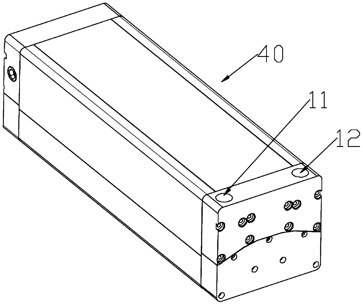
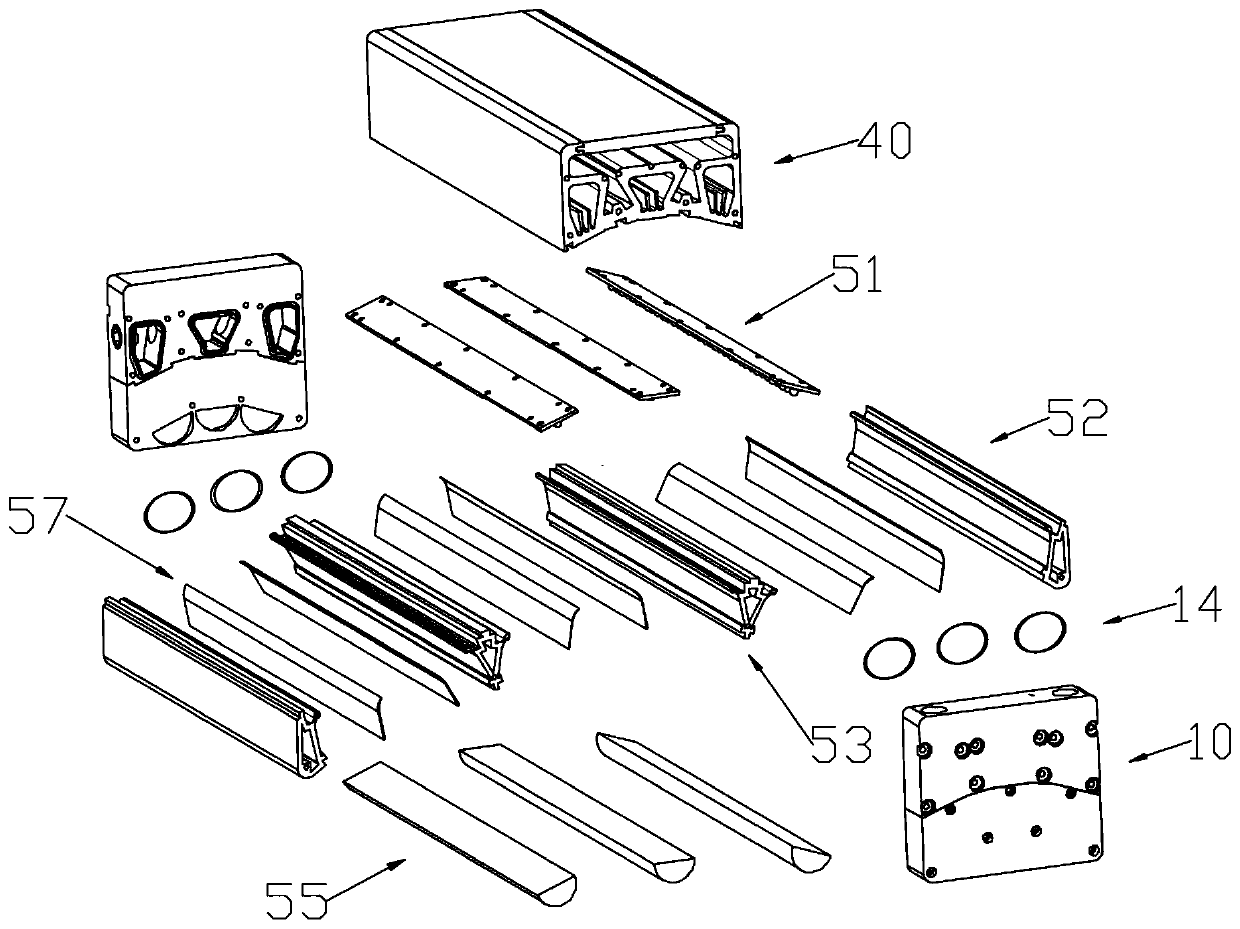
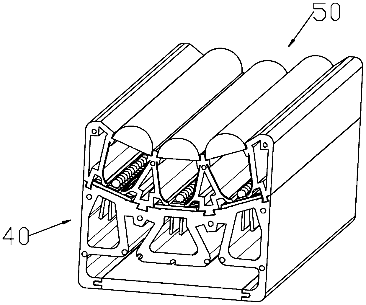
[0029] see Figure 1-Figure 10 , the present invention provides a focused LED light curing lamp, comprising: a plug 10, a heat dissipation housing 40, a light source 50 installed on the heat dissipation housing 40; the heat dissipation housing 40 is provided with a concave groove 41; The light source 50 includes: an LED light bar 51, a side concentrating part 52, a middle concentrating part 53, and a lens bar 55. The LED light bar 51, the side concentrating part 52, and the middle concentrating part 53 are all installed On the groove 41; the side light concentrating part 52 is provided with a first light concentrating concave surface 61, and the middle light concentrating part 53 is provided with two second light concentrating concave surfaces 54, and the first light concentrating concave surface of the side light concentrating part 61 and a...


PUM


Abstract

The invention discloses a focusing type LED photocuring lamp. The lamp comprises a plug, a heat dissipation shell and a light source installed on the heat dissipation shell; the heat dissipation shellis provided with a concave groove; the light source comprises an LED lamp strip, a side light condensation piece, middle light condensation pieces and a lens strip, and the LED lamp strip, the side light condensation piece and the middle light condensation piece are all installed on the groove. According to the focusing type LED photocuring lamp, the light gathering cover is defined by the side light gathering pieces and the adjacent middle light gathering pieces, the light gathering cover is defined by the two adjacent middle light gathering pieces, installation of the light gathering covercan be completed only by installing the side light gathering piece and the middle light gathering pieces on the heat dissipation shell, a special lantern ring does not need to be arranged to clamp thelight gathering cover, and installation is quite convenient, and especially for a heat dissipation shell with a cambered surface structure.

Description

technical field [0001] The invention relates to the technical field of light curing equipment, in particular to a focused LED light curing lamp. Background technique [0002] Curing light is an important part of light curing equipment. In order to increase the light intensity of the curing light, the light curing light adopts a structure with a curved surface, which can gather light, thereby enhancing the light intensity of the light curing light, such as the utility model patent of patent number CN210345149U. In order to reduce light scattering, the existing method is to use a condenser to concentrate the light. The existing condensers are all integrally formed. A lamp bead hole is set in the middle of the condenser, and the lamp bead is placed at the lamp bead hole. The condensing cover can concentrate the light emitted by the lamp beads, but the installation of this condensing cover requires additional special collars to clamp the condensing cover to prevent the condensi...

Claims


Application Information

Patent Timeline
Patent Type & Authority Applications(China)
IPC IPC(8): B05D3/06
CPCB05D3/067
Inventor 潘欲
Owner 深圳市云硕灯业有限公司
Why Eureka
Try Eureka