Wheelchair, brake unit therefor, and brake unit for a manually-propelled vehicle

a technology for manually-propelled vehicles and brake units, which is applied in the direction of electric devices, braking systems, tractors, etc., can solve the problems of user discomfort, user loss of body balance, and wheelchair movement in unexpected directions, so as to prevent user from losing body balance and simple configuration

Inactive Publication Date: 2006-12-05
TEAC CORP
View PDF16 Cites 25 Cited by
  • Summary
  • Abstract
  • Description
  • Claims
  • Application Information

AI Technical Summary

Benefits of technology

[0012]Accordingly, it is a general object of the present invention to provide a wheelchair, a brake unit therefor, and a brake unit for a manually-propelled wheelchair in which one or more of the above-described disadvantages are eliminated.
[0013]A more specific object of the present invention is to provide a brake unit that is easily attachable to a conventional manual wheelchair and manually-propelled vehicle so as to ensure the safety of its user with simple structure, and a wheelchair including such a brake unit.
[0017]According to the present invention, a necessary and sufficient braking force can be applied, with a simple configuration, to a manual wheelchair when a user stands up therefrom, thus ensuring, for instance, that the user is prevented from losing a body balance to totter or tumble in sitting down on the seat. Further, the brake unit according to the present invention is not only retrofittable to today's most widely used existing folding manual wheelchairs with ease, but also attachable so as not to hinder the folding of the wheelchair. Further, a lever is not pressed against the buttocks of the user so as to detect the user seated on the seat. As a result, causing discomfort to the user is prevented.

Problems solved by technology

Therefore, for instance, when a user such as an elderly person or a disabled person forgets to move the operating lever to the braking position, and touches the frame of a wheelchair to try to sit down thereon again after leaving the wheelchair, the wheelchair may start to move in an unexpected direction since no brakes are applied to the wheelchair.
Thus, if a wheelchair moves as a user sits down thereon, the user may lose a body balance so as to totter or tumble.
In the case of providing a lever mechanism that operates by receiving a load under a seat as described above, for instance, there is a problem in that the lever mechanism under the seat may prevent the wheels on both sides of a manual wheelchair, which are foldable in such directions as to approach each other, from being folded.
As a result, the user may feel discomfort.

Method used


Image

  • Wheelchair, brake unit therefor, and brake unit for a manually-propelled vehicle
  • Wheelchair, brake unit therefor, and brake unit for a manually-propelled vehicle
  • Wheelchair, brake unit therefor, and brake unit for a manually-propelled vehicle

Examples


first embodiment

[0037][First Embodiment]

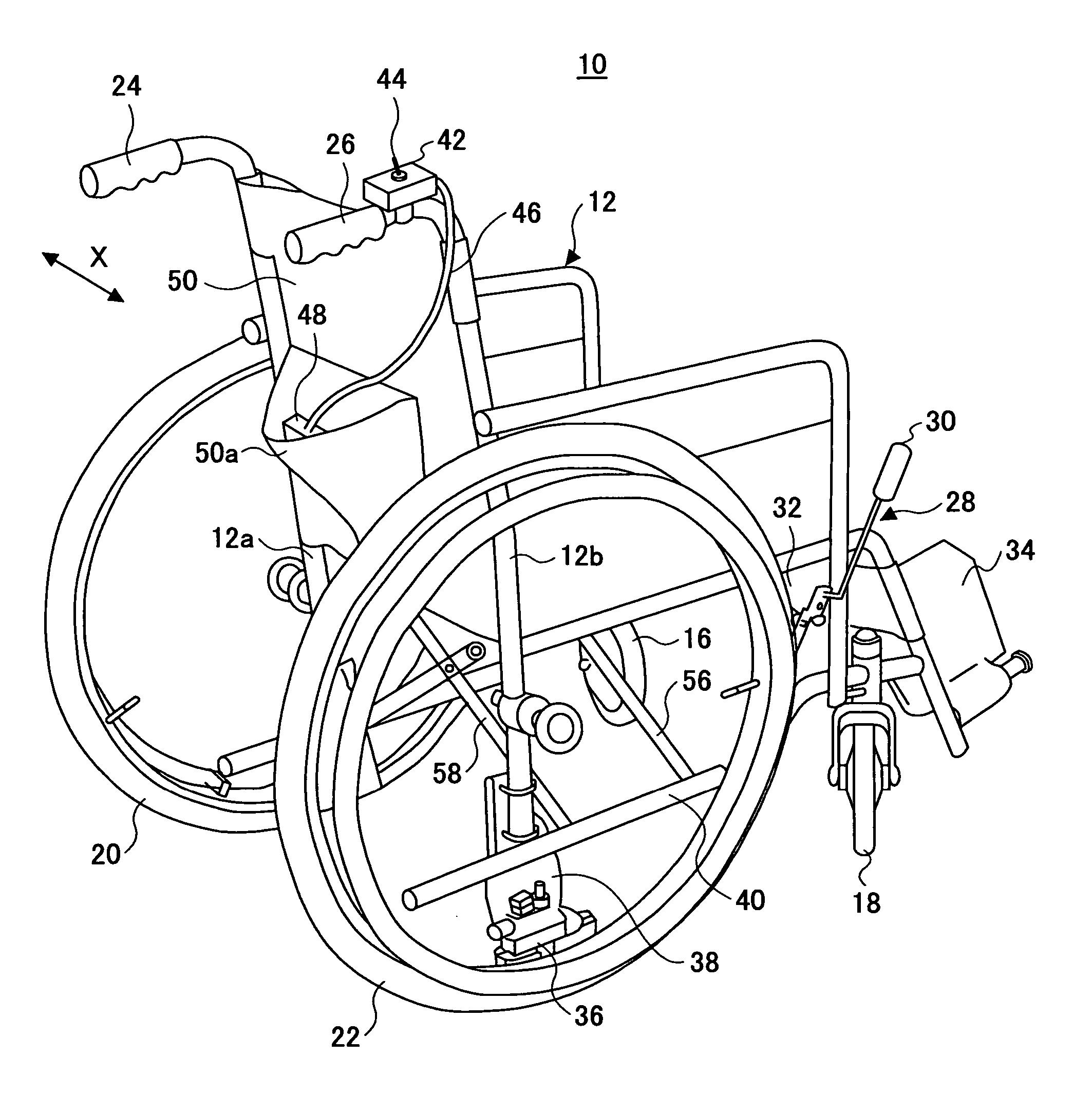
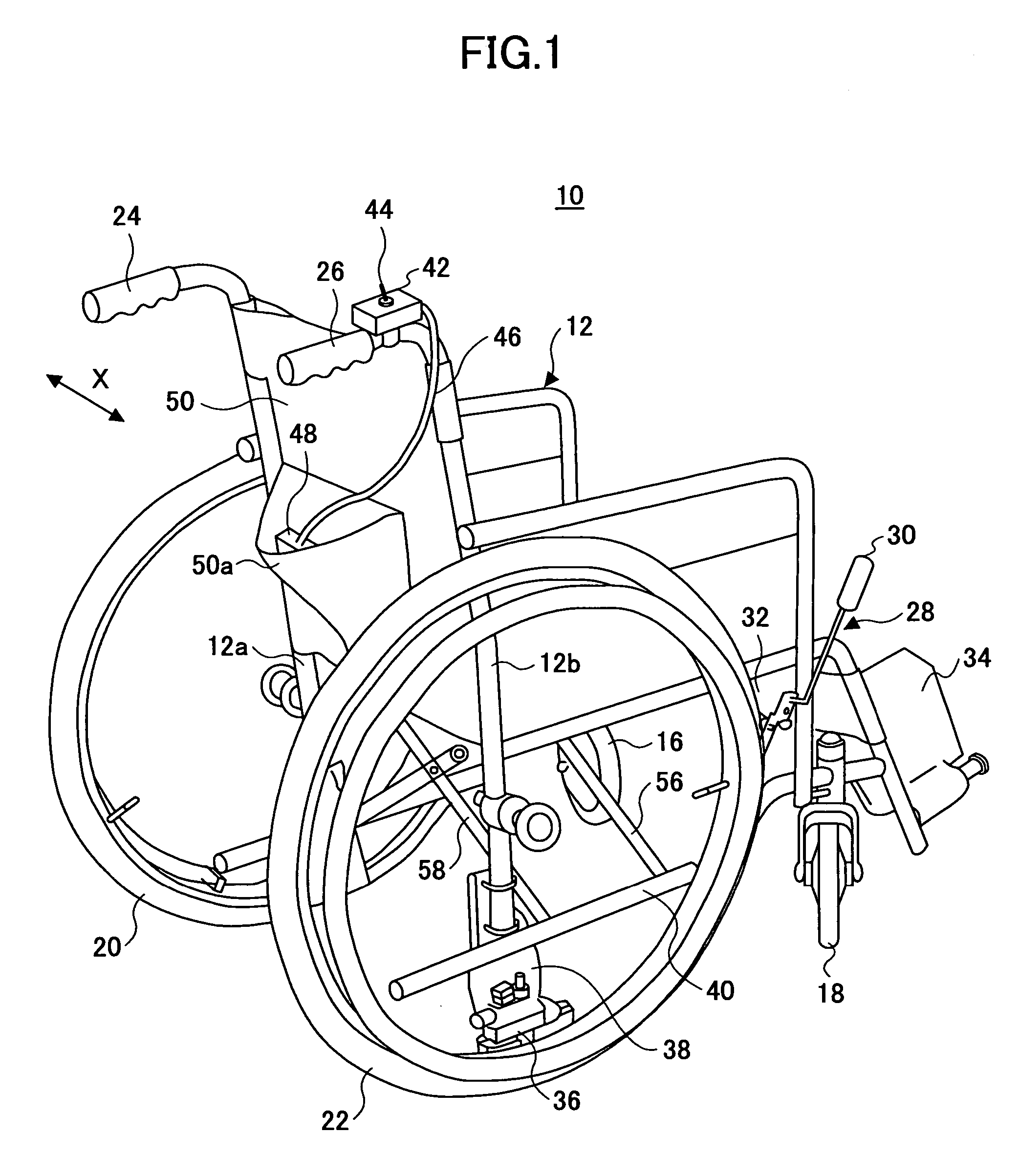
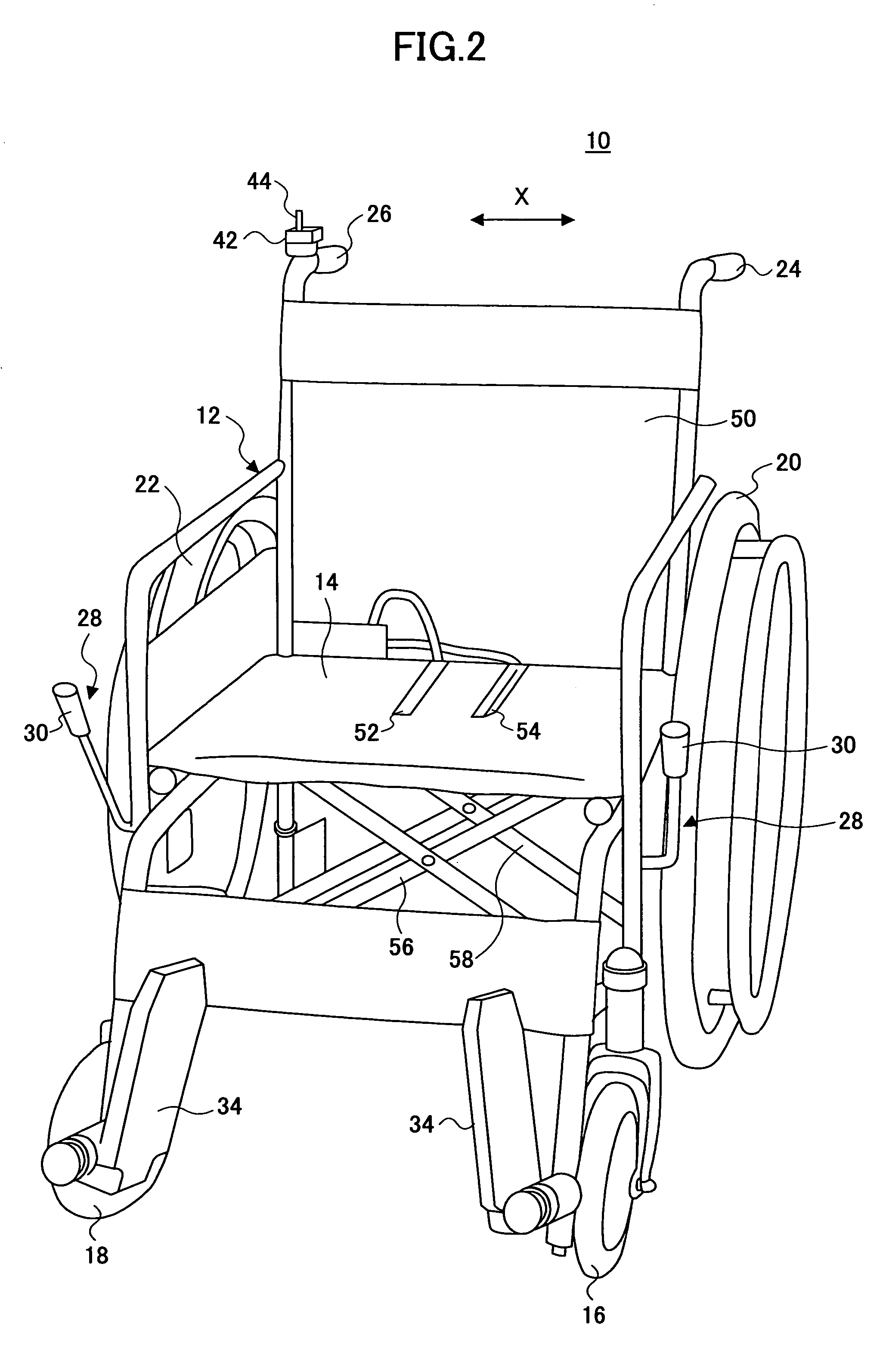
[0038]FIGS. 1 and 2 are an angled rear perspective view and a front perspective view, respectively, of a manually-propelled vehicle 10 according to a first embodiment of the present invention.

[0039]As shown in FIGS. 1 and 2, the manually-propelled vehicle 10, which is a four-wheel manual wheelchair in the illustrated exemplary embodiment, includes a frame 12 composed of metal pipes and a cloth seat 14 provided across the frame 12. Further, the manually-propelled vehicle 10 (hereinafter referred to as “wheelchair 10”) includes small-diameter front wheels 16 and 18 on the front side of the frame 12 and large-diameter rear wheels 20 and 22 on the respective left and right sides of the rear part of the frame 12. The front wheels 16 and 18 are provided to rotate freely so as to face a direction in which the wheelchair 10 moves.

[0040]The wheelchair 10 includes push handles 24 and 26 so that a caregiver can push the wheelchair 10 from behind. Further, the wheelchair...

second embodiment

[0165][Second Embodiment]

[0166]FIGS. 10 through 16 are plan views of an electric brake unit 120 according to a second embodiment of the present invention, showing an operation process of the electric brake unit 120. FIG. 17 is a circuit diagram showing a control circuit 122 according to the second embodiment. FIGS. 10 through 16 show an exemplary left-side electric brake unit 120, for use in, for example, the wheelchair 10 shown in FIGS. 1 and 2. The wheelchair 10 also includes the same electric brake unit 120 on the right side.

[0167]An exemplary configuration of the second embodiment may be realized by replacing the electric brake units 36 and the control circuit 108 of the first embodiment with the electric brake units 120 and the control circuit 122. The same elements as those of the first embodiment are referred to by the same numerals, and a description thereof is omitted. The mechanical drive part of the electric brake unit 120 including the brake shoes 64a and 66a that are no...


PUM


Abstract

A wheelchair is disclosed that includes a seat, a pair of wheels, a detection part indicating the presence or absence of a user on the seat, electric brake units switching between applying braking forces to and releasing braking forces from the wheels based on control signals, and a control part connected to the detection part and the electric brake units and outputting the control signals to the electric brake units. The control signals include a first control signal causing the braking forces by the electric brake units to be applied to the wheels and a second control signal causing the braking forces by the electric brake units to be released therefrom. The first control signal is output when the detection part indicates the absence of the user on the seat, and the second control signal is output when the detection part indicates the presence of the user on the seat.

Description

BACKGROUND OF THE INVENTION[0001]1. Field of the Invention[0002]The present invention relates generally to wheelchairs, brake units therefor, and brake units for manually-propelled vehicles, and more particularly to a brake unit that is attached to a manual wheelchair or a manually-propelled vehicle so as to increase its safety when a person leaves or sits down on its seat, and a wheelchair including such a brake unit.[0003]2. Description of the Related Art[0004]Normally, a manual brake unit is provided on each of the right and left sides of a manual wheelchair. The manual brake units are provided in front of corresponding right and left rear wheels, and enter in a braking state to brake the rear wheels or in a brake releasing state to release the brakes, depending on the operation position of an operating lever.[0005]For instance, when a user (a care receiver) seated on the seat of the wheelchair rises from the seat, the user is required to stand up after moving the operating lever...

Claims


Application Information

Patent Timeline
Patent Type & Authority Patents(United States)
IPC IPC(8): B62M1/14A61G5/02A61G5/10B60K28/04B62B5/04F16D55/02B60T1/06B60T13/74F16D65/14
CPCA61G5/10A61G5/1016B60T1/06B60T13/74A61G5/101A61G5/1035A61G5/1067B62B5/0409B62B5/0476F16D2121/24F16D2125/30F16D2125/48F16D2125/52F16D2127/08A61G5/1018
Inventor WAKITA, TOYOAKINOZAWA, TAKAOTAKAGI, KIYOSHI
Owner TEAC CORP
Why Eureka
Try Eureka