Centrifugal compressor having a flexible coupling

a centrifugal compressor and flexible technology, applied in the direction of mechanical equipment, non-positive displacement pumps, liquid fuel engines, etc., can solve the problem that the components in the shaft line of the compressor unit remain mechanically uncoupled

Active Publication Date: 2006-12-05
THERMODYN
View PDF11 Cites 72 Cited by
  • Summary
  • Abstract
  • Description
  • Claims
  • Application Information

AI Technical Summary

Benefits of technology

[0009]It can then be seen that it is then possible to eliminate the alignment problems of the driving and driven shafts that would make it impossible to use this system. Furthermore, th...

Problems solved by technology

Furthermore, the vibrational behaviours specific to the rotor and the compressor shaft are unchanged...

Method used


Image

  • Centrifugal compressor having a flexible coupling
  • Centrifugal compressor having a flexible coupling
  • Centrifugal compressor having a flexible coupling

Examples


Embodiment Construction

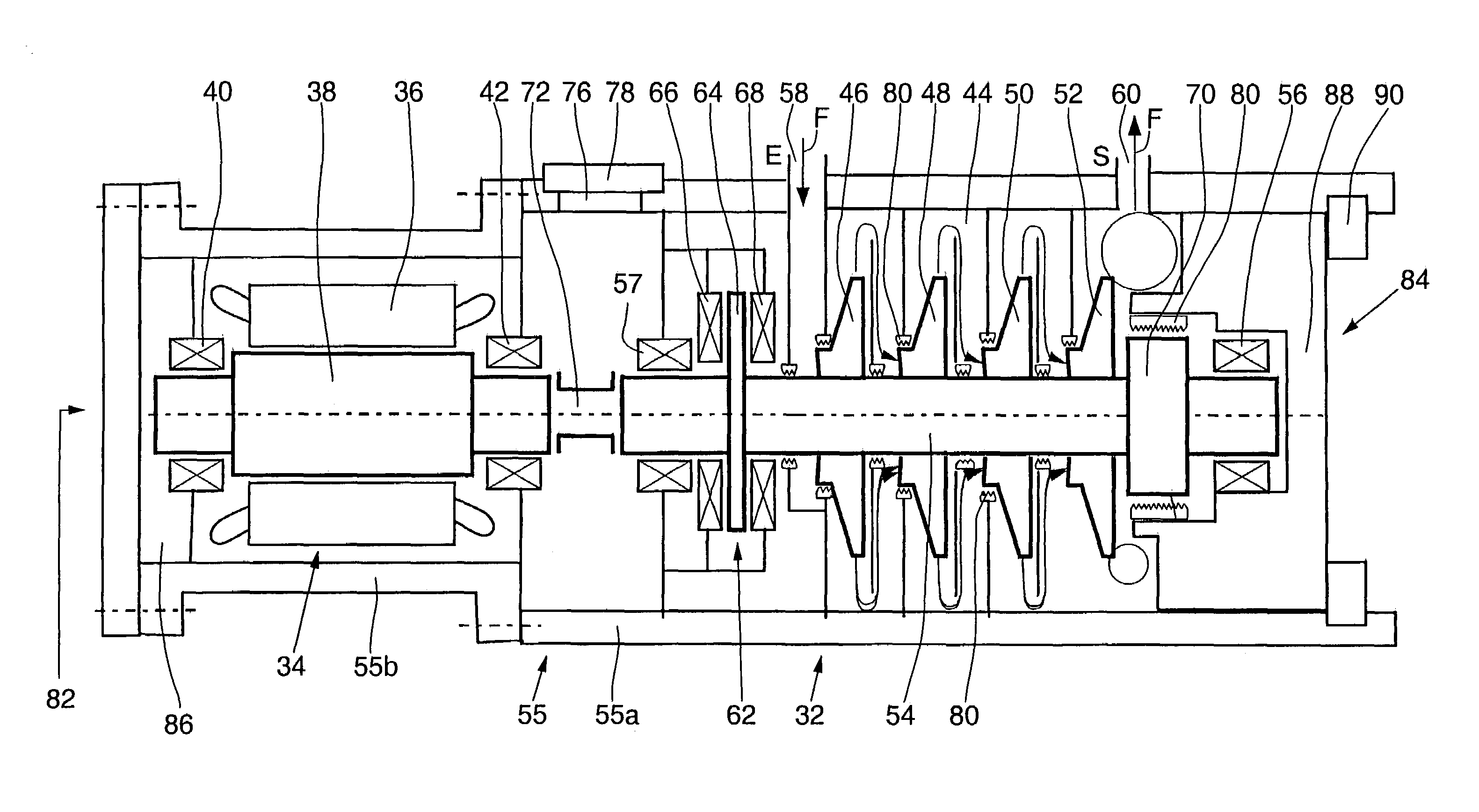
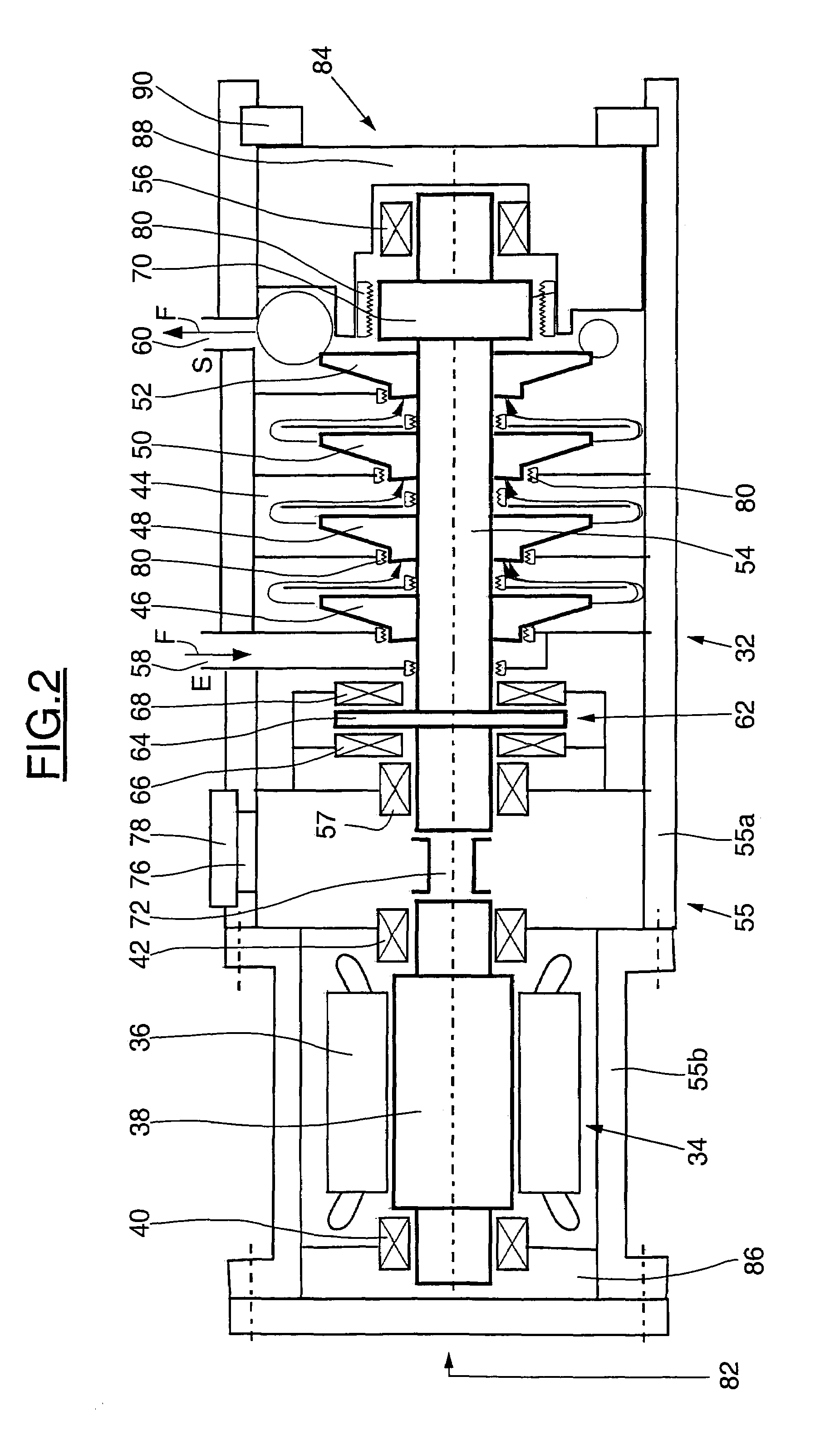
[0021]With reference to FIG. 2, a motor-compressor conform with the invention, denoted by the general numeric reference 32, comprises essentially an electric motor 34 with a high rotation speed (6000 to 16000 rpm) supplied by a frequency variator and comprising a stator 36 and a rotor 38 supported by two end bearings 40 and 42, and a compressor unit 44 comprising a set of bladed wheels 46, 48, 50 and 52, installed on a driven shaft 54. The assembly is installed on a base (not shown) and is arranged in a common casing 55 tight to the gas manipulated by the turbocompressor.

[0022]Obviously, the motor compressor unit 44 may comprise an arbitrary number of such bladed wheels, or as described below, may comprise a different arrangement of bladed wheels.

[0023]As can be seen in FIG. 2, the casing is composed of an assembly of casing elements fixed together such as 55a and 55b, each providing the support and protection of the motor or a compression stage and fixed together by appropriate att...


PUM


Abstract

This compressor unit comprises a motor (34) and at least one compressor (44) comprising a driven shaft (54) driven by the rotor of the motor and bladed wheels fitted on the driven shaft (54), the assembly composed of the motor and the compressor being installed in a common casing (55) leak tight to the gas manipulated by the compressor unit. The rotor and the driven shaft are connected through a flexible coupling (72) placed in the casing.

Description

BACKGROUND OF THE INVENTION[0001]The invention relates to a turbocompressor or motor-compressor, and particularly to an integrated motor compressor unit.[0002]With reference to FIG. 1, integrated motor-compressor units comprise a sealed common casing 10 in which there is an electric motor 12 and a compressor unit 14, for example a multi-stage compressor unit, which comprises a set of bladed wheels like the bladed wheel 16 fitted on a shaft 18. The motor 12 drives a rotor 20 in rotation, this rotor 20 being coupled to the shaft 18 of the compressor 14 through a rigid coupling 22. Bearings 24, 26 and 28 are used to support the shaft line of the motor compressor unit. The assembly is placed in a common casing 29.[0003]During operation, the gas to be manipulated is present at the inlet E of the turbocompressor and is then transmitted to the successive compression stages of the compressor unit to be delivered at the outlet S. An axial bearing block 30 is used to prevent axial displacemen...

Claims


Application Information

Patent Timeline
IPC IPC(8): F04B17/03F04B25/00F04D17/12F04D25/02F04D25/06F04D29/04F04D29/058
CPCF04D17/125F04D25/02F04D25/0606F04D29/058F04D25/022F04D29/054
Inventor PUGNET, JEAN-MARCFRIEZ, PATRICKLABOUBE, PIERRE
Owner THERMODYN
Why Eureka
Try Eureka