Apparatus for hardening a cylindrical bearing on a shaft by means of induction heating utilizing an elastic element

a technology of elastic elements and cylindrical bearings, applied in the direction of induction heating, induction heating apparatus, furnace types, etc., can solve the problems of reducing both the design and the susceptibility to faults, and achieve the effect of reducing the outlay on the apparatus

Active Publication Date: 2006-12-05
MASCHFAB ALFING KESSLER
View PDF3 Cites 9 Cited by
  • Summary
  • Abstract
  • Description
  • Claims
  • Application Information

AI Technical Summary

Benefits of technology

[0005]Therefore, the present invention is based on the object of avoiding electrical cross-connections, which are susceptible to faults, reducing the outlay on apparatus when providing a hardening apparatus and a hardening process which allow hardening even of transition radii that are of undercut design in a structurally simple manner and without the need for a second heating unit.
[0007]Unlike in the prior art, in which two heating units having two inductors are provided and have to be displaced in their entirety, as complete units, in the axial direction in order for the radius hardening branches to be introduced into the undercut transition radii, in the solution according to the invention only a single heating unit with associated inductor is required. According to the invention, the axial displaceability of the radius hardening branches to allow them to be introduced into the transition radii is achieved by virtue of the current-carrying elements being correspondingly elastic, thereby allowing the required relative movement. Instead of power cables as current-carrying elements, the current-carrying elements are now designed, according to the invention, in such a way that they simultaneously also support the radius hardening branches. Nevertheless, they are configured in such a manner as to permit axial displacement movement. Unlike in the prior art, therefore, it is no longer necessary for the entire heating unit together with the inductor to be displaced, but rather it is merely necessary for the radius hardening branches to be displaced in the axial direction relative to the associated bearing-surface hardening branch and therefore also the associated inductor, so that they can move into the transition radii. This means that the masses which have to be moved are significantly lower, which reduces both the outlay on design and the susceptibility to faults.
[0010]Configuring the current-carrying elements in each case in the form of a loop, which may preferably take the shape of a tuning fork, makes it possible, in conjunction with a suitable selection of materials, to achieve a sufficient elasticity for axial displacement of the radius hardening branches. In general, copper, which has a suitable elasticity, is used for the current-carrying elements.
[0011]If, in a highly advantageous configuration, the current-carrying elements are configured as hollow profiled sections, preferably in tube, plate or strip form, it is simultaneously also possible for coolant to be supplied and discharged in the interior of the current-carrying elements. This eliminates the need for separate coolant lines.

Problems solved by technology

This means that the masses which have to be moved are significantly lower, which reduces both the outlay on design and the susceptibility to faults.

Method used


Image

  • Apparatus for hardening a cylindrical bearing on a shaft by means of induction heating utilizing an elastic element
  • Apparatus for hardening a cylindrical bearing on a shaft by means of induction heating utilizing an elastic element
  • Apparatus for hardening a cylindrical bearing on a shaft by means of induction heating utilizing an elastic element

Examples


Embodiment Construction

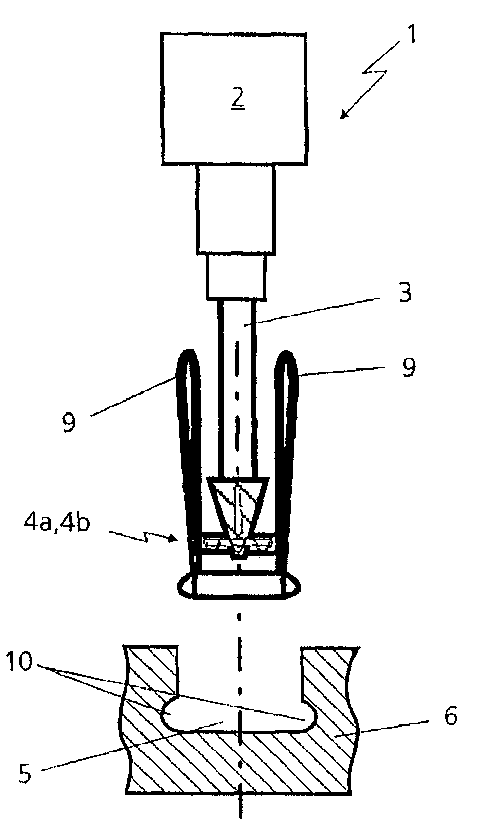
[0022]The apparatus explained below for hardening cylindrical bearing locations on a shaft, in particular a crankshaft, is fundamentally of a known design, and consequently only those parts which are pertinent to the invention are dealt with in more detail. Reference should be made, for example, to U.S. Pat. No. 6,399,928 for details as to the structure and mode of action of a hardening process and apparatus. The hardening apparatus has a heating unit 1 with a power supply device 2 and an inductor 3, which is connected to the power supply device 2. At the lower end, the inductor has two heating conductor arms 4a and 4b, also known as heating conductor loops (cf. FIG. 6), which engage around the circumferential side of a bearing location 5 that is to be hardened on a crankshaft 6, only part of which is illustrated; they engage around less than 180 degrees of the circumferential side.

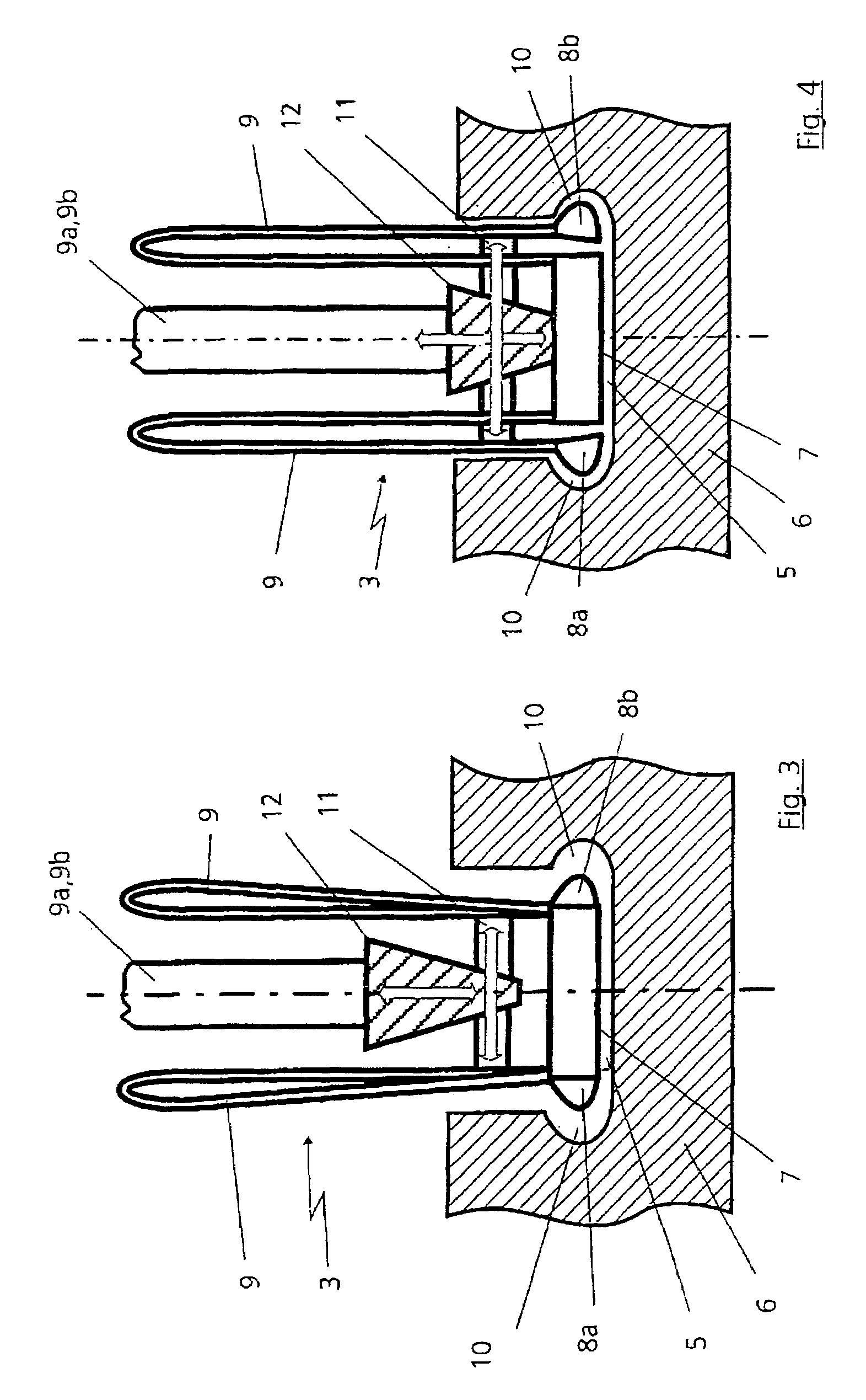
[0023]Each heating conductor arm 4a and 4b is provided with a bearing-surface hardening branch 7 and t...


PUM

PropertyMeasurementUnit
shapeaaaaaaaaaa
axial displacementaaaaaaaaaa
mechanicalaaaaaaaaaa

Abstract

An apparatus for hardening cylindrical bearing locations on a shaft, in particular a crankshaft, in which transition radii to the adjacent shaft parts are of undercut design, is provided with a heating unit, which is connected to a power supply, and with an inductor. The inductor has two heating conductor arms, which are arranged at a distance from one another and each run in the peripheral direction of the bearing location that is to be hardened. Each of the two heating conductor arms is provided with an inner bearing-surface hardening branch and two outer radius hardening branches, the bearing-surface hardening branch in each case being mechanically connected to the radius hardening branches by current-carrying elements which bear the radius hardening branches. The mechanical connection is sufficiently elastic for the radius hardening branches to be displaceable relative to the bearing-surface hardening branch in the axial direction of the shaft that is to be hardened.

Description

BACKGROUND OF THE INVENTION[0001]1. Field of the Invention[0002]The invention relates to an apparatus for hardening cylindrical bearing locations on a shaft, in particular a crankshaft, in which transition radii to the adjacent shaft parts are of undercut design. The invention also relates to a process for hardening cylindrical bearing locations of this type.[0003]2. Description of the Related Art[0004]U.S. Pat. No. 6,399,928 has illustrated and described an apparatus for hardening cylindrical bearing locations on a shaft, two independent heating units, each having an inductor, being provided. Each inductor is in this case provided with two heating conductor arms arranged at a distance from one another. Each of the two heating conductor arms has an outer heating conductor branch and an inner heating conductor branch. The bearing surface of the bearing location that is to be hardened is hardened using the inner heating conductor branches and the undercut transition radii are hardened...

Claims


Application Information

Patent Timeline
Patent Type & Authority Patents(United States)
IPC IPC(8): H05B6/10H05B6/40
CPCC21D1/10C21D9/30H05B6/40C21D9/28C21D2221/02Y02P10/25
Inventor ZAHN, ANDREASGERBETH, RALPH
Owner MASCHFAB ALFING KESSLER
Why Eureka
Try Eureka