Multilayer capacitor

a multi-layer capacitor and capacitor technology, applied in the direction of capacitors, basic electric elements, coils, etc., can solve the problems of difficult to increase the equivalent series resistance, the multi-layer capacitor cannot exhibit the desirable magnitude of equivalent series resistance, and the mounting direction is critical, so as to achieve the effect of increasing the equivalent series resistance and being easy to moun

Active Publication Date: 2006-12-05
TDK CORPARATION
View PDF5 Cites 41 Cited by
  • Summary
  • Abstract
  • Description
  • Claims
  • Application Information

AI Technical Summary

Benefits of technology

[0007]It is an object of the present invention to provide a multilayer capaci

Problems solved by technology

However, when mounting such a multilayer capacitor to a substrate or the like, the mounting direction is critical.
Namely, since such a multilayer capacitor increases its equivalent series resistance by connecting inner conductors to outer conductors which are not connected to land patterns of the substrate or the like, it becomes difficult for the multil

Method used


Image

  • Multilayer capacitor
  • Multilayer capacitor
  • Multilayer capacitor

Examples


first embodiment

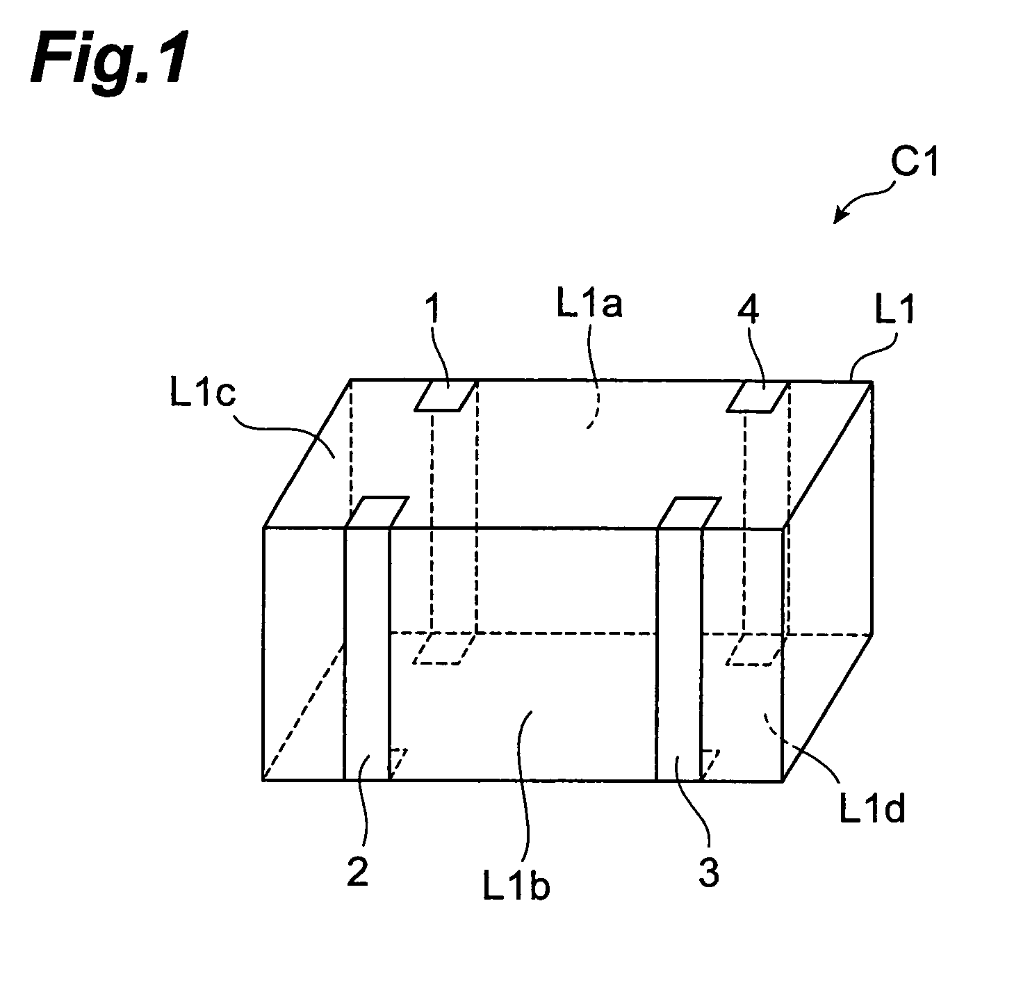
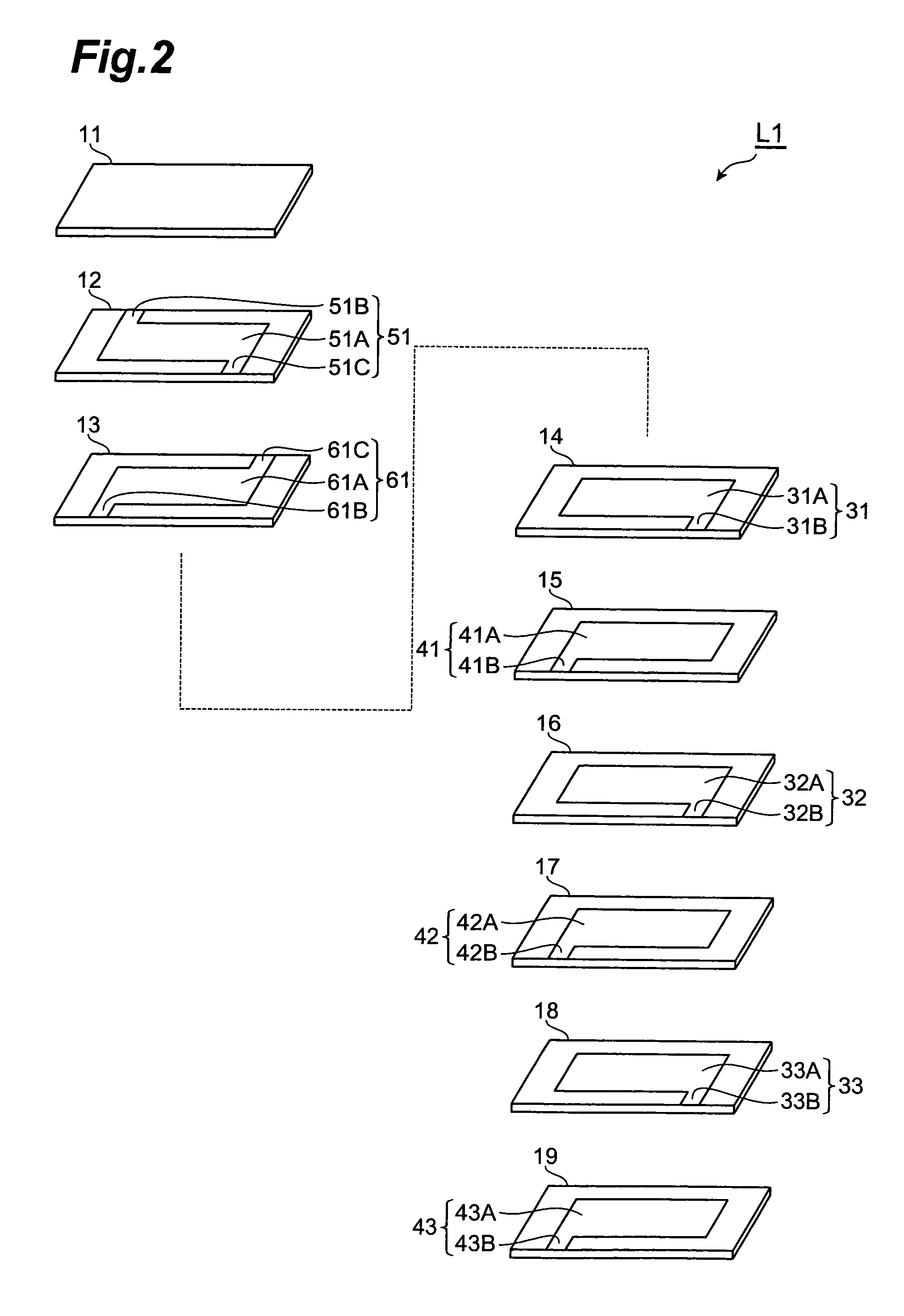
[0052]With reference to FIGS. 1 and 2, the structure of the multilayer capacitor C1 in accordance with a first embodiment will be explained. FIG. 1 is a perspective view of the multilayer capacitor in accordance with the first embodiment. FIG. 2 is an exploded perspective view of the multilayer body included in the multilayer capacitor in accordance with the first embodiment.

[0053]As shown in FIG. 1, the multilayer capacitor C1 in accordance with the first embodiment comprises a multilayer body L1 having a substantially rectangular parallelepiped form, and four outer conductors formed on side faces of the multilayer body L1. The four outer conductors are a first outer conductor 1, a second outer conductor 2, a third outer conductor 3, and a fourth outer conductor 4. The four outer conductors are formed so as to be electrically insulated from each other on the surface of the multilayer body L1.

[0054]Both of the first outer conductor 1 and fourth outer conductor 4 are positioned on a ...

second embodiment

[0094]With reference to FIGS. 10 and 11, the structure of the multilayer capacitor in accordance with a second embodiment will be explained. The multilayer capacitor in accordance with the second embodiment differs from the multilayer capacitor C1 in accordance with the first embodiment in terms of the arrangement of outer conductors in the multilayer body. FIG. 10 is a perspective view of the multilayer capacitor in accordance with the second embodiment. FIG. 11 is an exploded perspective view of the multilayer body included in the multilayer capacitor in accordance with the second embodiment.

[0095]As shown in FIG. 10, the multilayer capacitor C2 in accordance with the second embodiment comprises a multilayer body L2 having a substantially rectangular parallelepiped form, and four outer conductors formed on side faces of the multilayer body L2. The four outer conductors are a first outer conductor 1, a second outer conductor 2, a third outer conductor 3, and a fourth outer conducto...

third embodiment

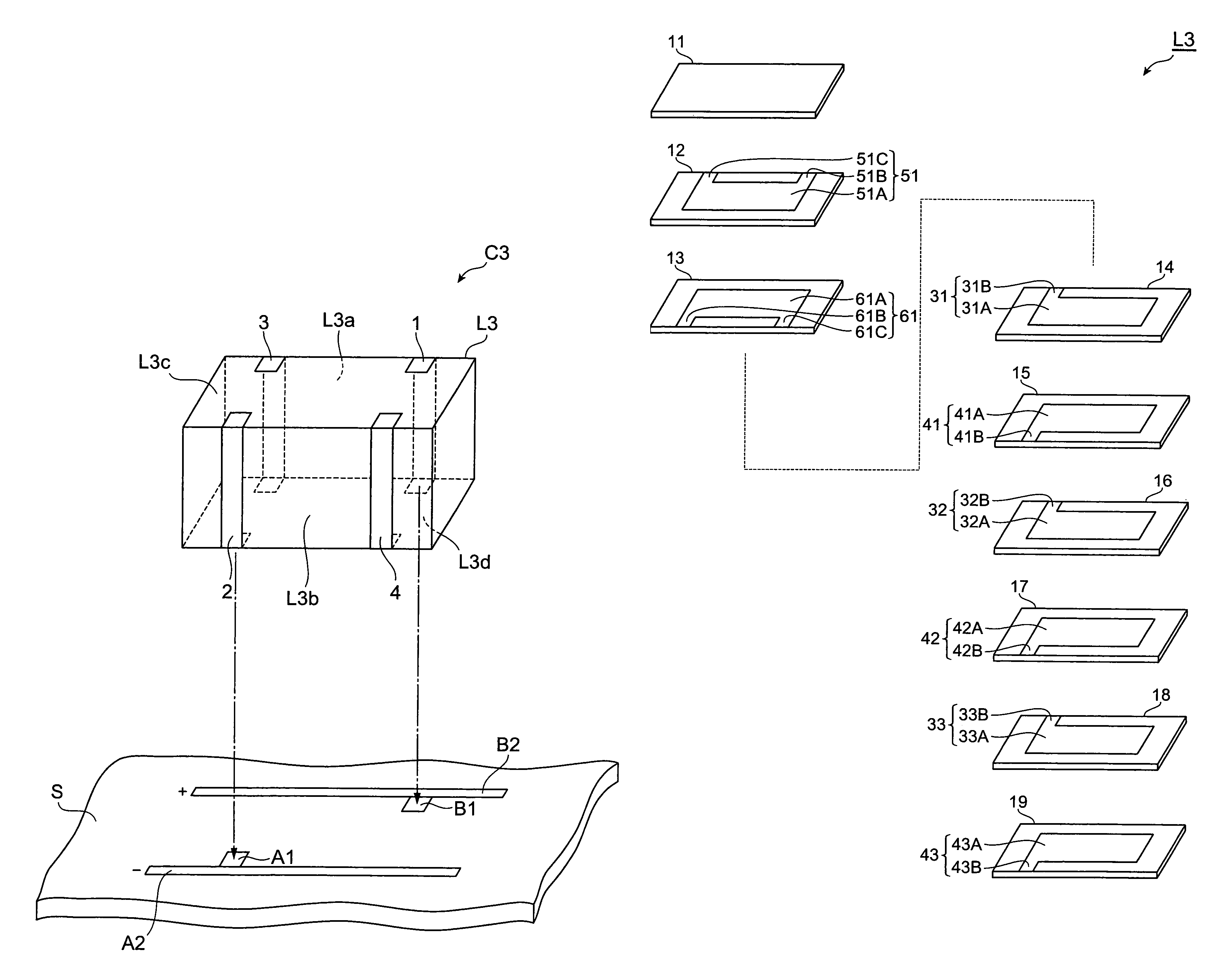
[0121]With reference to FIGS. 12 and 13, the structure of the multilayer capacitor in accordance with a third embodiment will be explained. The multilayer capacitor in accordance with the third embodiment differs from the multilayer capacitor C1 in accordance with the first embodiment in terms of the arrangement of outer conductors in the multilayer body. FIG. 12 is a perspective view of the multilayer capacitor in accordance with the third embodiment. FIG. 13 is an exploded perspective view of the multilayer body included in the multilayer capacitor in accordance with the third embodiment.

[0122]As shown in FIG. 12, the multilayer capacitor C3 in accordance with the third embodiment comprises a multilayer body L3 having a substantially rectangular parallelepiped form, and four outer conductors formed on side faces of the multilayer body L3. The four outer conductors are a first outer conductor 1, a second outer conductor 2, a third outer conductor 3, and a fourth outer conductor 4. ...


PUM


Abstract

A multilayer capacitor comprises a multilayer body in which a plurality of dielectric layers are laminated, and first to fourth outer conductors formed on the multilayer body. The multilayer body includes first to fourth inner conductors. The first and second inner conductors have respective regions opposing each other with at least one dielectric layer in between. The first and second inner conductors are connected to the third and second outer conductors respectively. The third inner conductor is connected to the first and third outer conductors, and the fourth inner conductor is connected to the second and fourth outer conductors. Two outer conductors and the remaining two outer conductors are respectively formed on first and second side faces of the multilayer body which oppose each other and are parallel to an opposing direction of the first and second inner conductors.

Description

BACKGROUND OF THE INVENTION[0001]1. Field of the Invention[0002]The present invention relates to a multilayer capacitor.[0003]2. Related Background Art[0004]Known as this kind of multilayer capacitor is one comprising a multilayer body which is formed with a plurality of laminated dielectric layers and includes a plurality of inner conductors, and a plurality of outer conductors formed on the multilayer body.[0005]Power supplies for central processing units (CPUs) mounted in digital electronic devices have been increasing their load current while lowering their voltage. Therefore, it has become very difficult to suppress the fluctuation in power supply voltage under a tolerable level in response to a drastic change in load current, whereby a multilayer capacitor known as decoupling capacitor has come into connection with a power supply. At the time when the load current fluctuates transiently, the multilayer capacitor supplies a current to the CPU, thereby suppressing the fluctuatio...

Claims


Application Information

Patent Timeline
IPC IPC(8): H01F5/00
CPCH01G4/232H01G4/30
Inventor TOGASHI, MASAAKIBURKET, CHRIS T.
Owner TDK CORPARATION
Why Eureka
Try Eureka