Seamless tiled display system

a display system and seamless technology, applied in static indicating devices, instruments, non-linear optics, etc., can solve the problems of size and resolution requirements, impracticality of simply adapting existing display technologies to meet the needs of such higher-end display applications, and the size and resolution of lcds are both limited

Inactive Publication Date: 2006-12-05
HONEYWELL INT INC
View PDF24 Cites 48 Cited by
  • Summary
  • Abstract
  • Description
  • Claims
  • Application Information

AI Technical Summary

Problems solved by technology

While many applications are well served by these existing displays, there are other applications with size and resolution requirements that are not met by any single display.
Unfortunately, various factors make it impractical to simply adapt existing display technologies to meet the needs of such higher-end display applications.
For example, the size and resolution of LCDs are both limited by manufacturing and yield issues, and by the need to provide control signals to each pixel within the LCD.
Because of the limits on the size and resolution of existing displays, the ability to design larger and higher-resolution displays to effectively present large amounts of information is limited.
Such systems, however, tend to contain visually disturbing seams between the tiles resulting from the gaps between adjacent pixels on adjacent tiles, and from any components (e.g., interconnects, adhesives, seals, mechanical alignment components, etc.) located between adjacent tiles.
Such systems, unfortunately, suffer from several problems.
One problem is that the depth or thickness of such systems may be relatively large due to the limited practical field of view of the single projection lens, which requires that the distance from the lens to its associated FPD tile be proportional to the size of that FPD tile.
If, for example, each FPD tile comprises an LCD having 1280×1024 pixels in a 338×270 mm viewing area (i.e., 3.8 dots / mm), the distance of the single projection lens from the LCD must be proportional to the relatively large size of the LCD, which will hamper efforts to make the system thin.
Another problem is that the projection lens may require high-quality optical characteristics to meet minimal system resolution and distortion requirements, which is expensive.

Method used


Image

  • Seamless tiled display system
  • Seamless tiled display system
  • Seamless tiled display system

Examples


examples

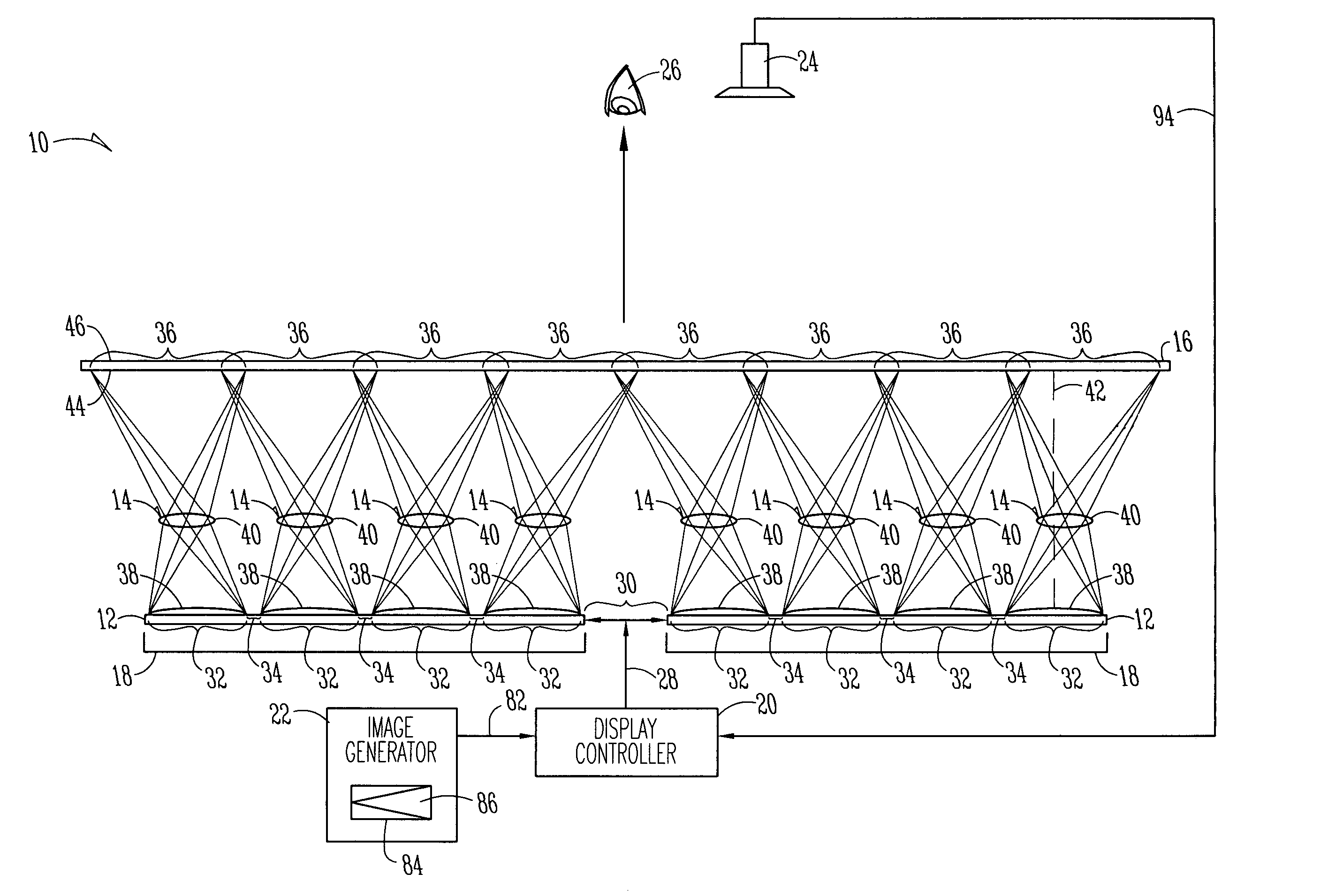
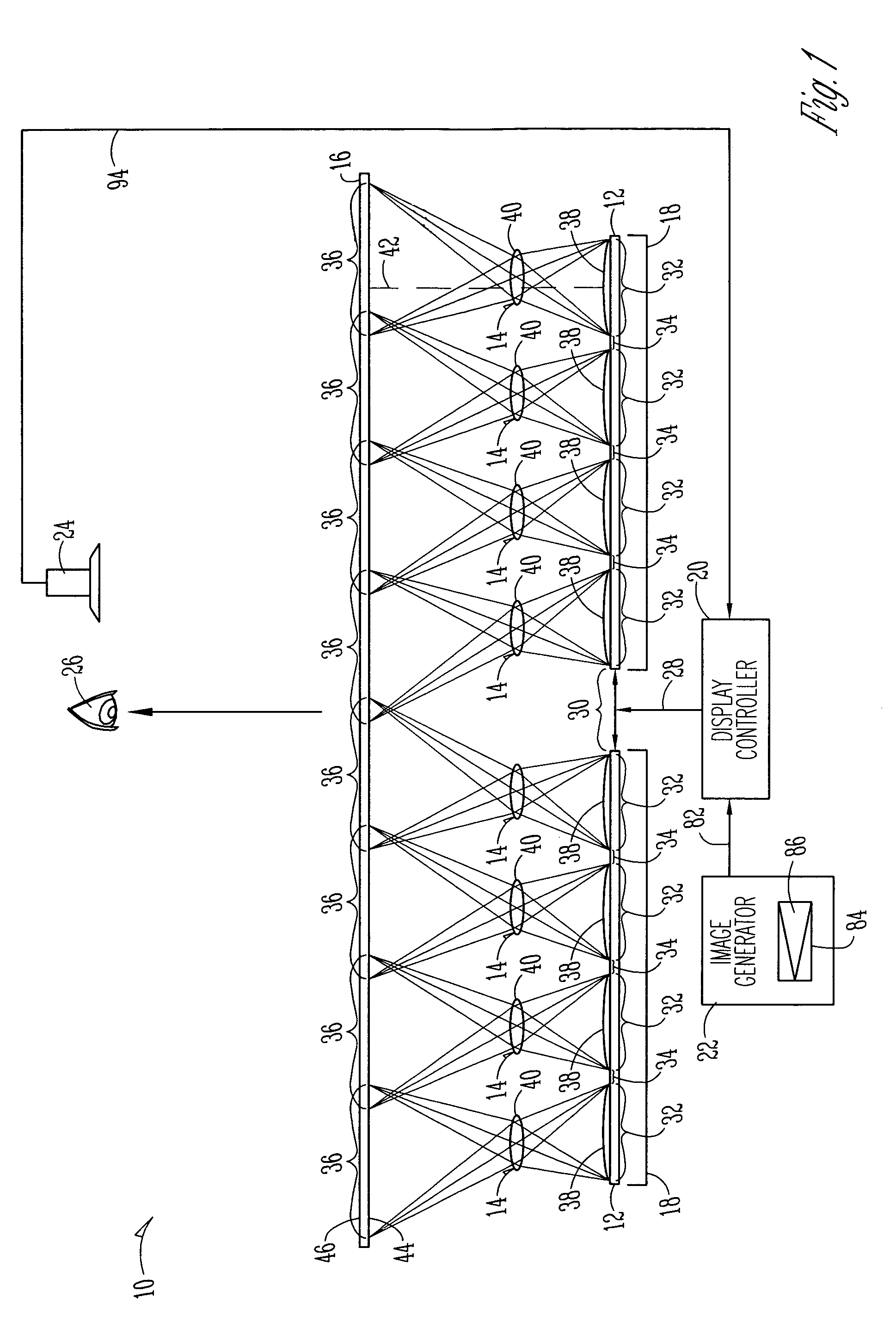
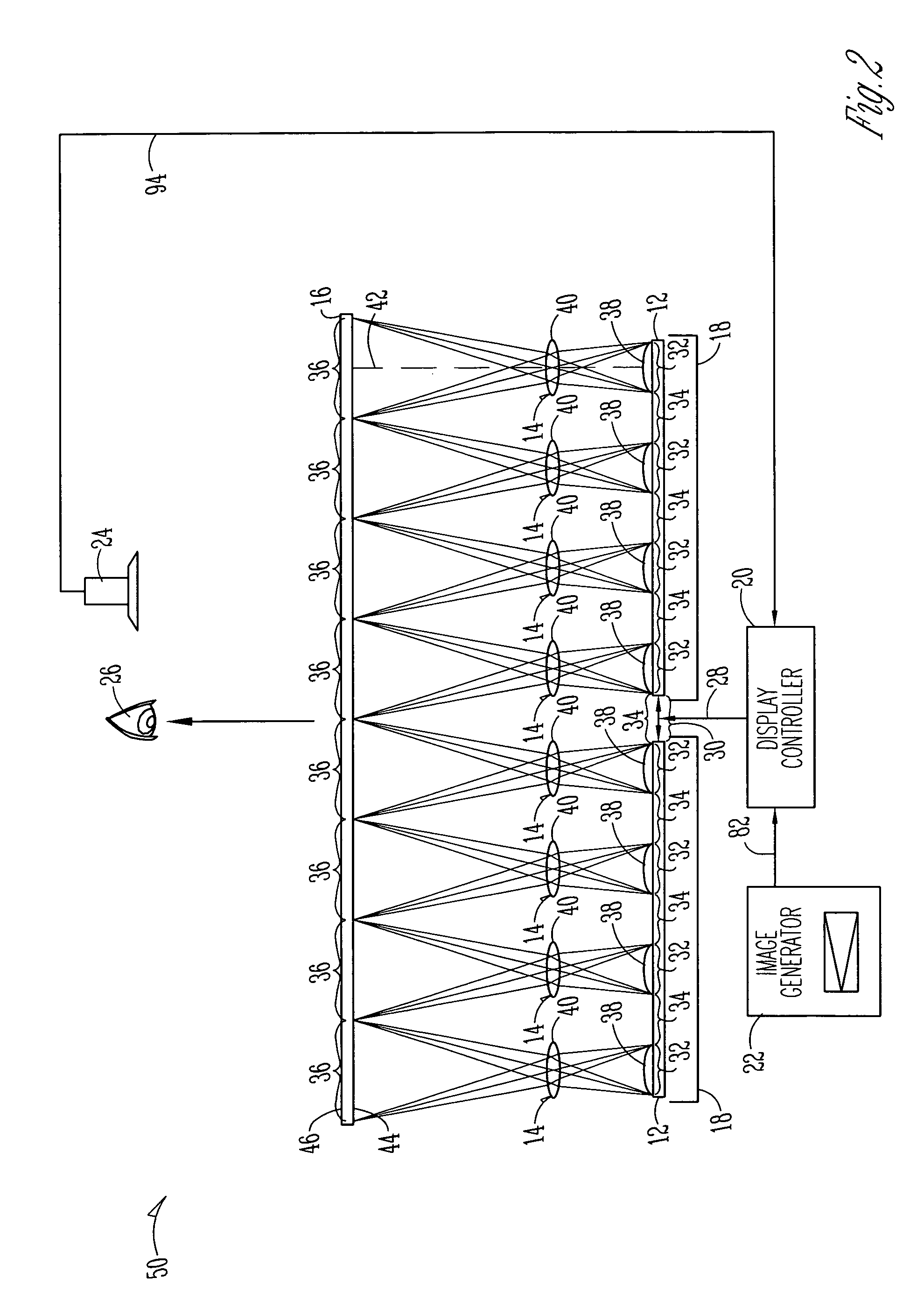
[0065]Other exemplary optical systems for use in the present invention are shown in FIGS. 6–8. The systems in the examples of FIGS. 6 and 7 are configured to project the sectional images displayed on one of display devices 12 onto screen 16. Thus, a tiled display system would use one of these optical systems per display device 12. The optical system shown in FIG. 8 is configured to project one sectional image on one of display devices 12. Thus, a tiled display system would use a plurality of these unit optical cells per display device 12.

[0066]In creating these examples, a number of design assumptions and constraints were used, including: each display device 12 will comprise a Samsung SyncMaster 700 TFT panel, which has 1280×1024 pixels in a 338 mm×270 mm viewable area, for a pitch of 3.8 pixels / mm; a 12 mm dead-band will be around each LCD; root-mean-square (RMS) spot size (diameter) will be less than the pixel size; the total thickness of the system will be less than 100 mm (not i...


PUM

PropertyMeasurementUnit
sizeaaaaaaaaaa
total thicknessaaaaaaaaaa
diameteraaaaaaaaaa

Abstract

A modular and scalable seamless tiled display apparatus includes multiple display devices, a screen, and multiple lens assemblies. Each display device is subdivided into multiple sections, and each section is configured to display a sectional image. One of the lens assemblies is optically coupled to each of the sections of each of the display devices to project the sectional image displayed on that section onto the screen. The multiple lens assemblies are configured to merge the projected sectional images to form a single tiled image. The projected sectional images may be merged on the screen by magnifying and shifting the images in an appropriate manner. The magnification and shifting of these images eliminates any visual effect on the tiled display that may result from dead-band regions defined between each pair of adjacent sections on each display device, and due to gaps between multiple display devices.

Description

STATEMENT REGARDING FEDERALLY SPONSORED RESEARCH OR DEVELOPMENT[0001]This invention was made with Government support under contract NAS1-20219 awarded by NASA. The Government has certain rights in this invention.FIELD OF THE INVENTION[0002]The present invention generally relates to the field of displays, and more particularly relates to seamless tiled display systems including multiple display devices (i.e., tiles) tiled together via projection to produce a larger and / or higher-resolution image.BACKGROUND[0003]Many types of displays are commercially available in a variety of sizes and resolutions. These known types of displays include flat-panel displays (FPDs), such as liquid crystal displays (LCDs), plasma displays and organic light-emitting diode (OLED) displays, and non-FPDs, such as cathode ray tube (CRT) displays and projection displays.[0004]While many applications are well served by these existing displays, there are other applications with size and resolution requirements t...

Claims


Application Information

Patent Timeline
Patent Type & Authority Patents(United States)
IPC IPC(8): G02F1/133G02F1/1333G02F1/1335
CPCG02F1/13336G02F1/133526
Inventor DUBIN, MATTHEW B.LARSON, BRENT D.KOLOSOWSKY, ALEKSANDRA
Owner HONEYWELL INT INC
Why Eureka
Try Eureka