Efficient optical coherence tomography (OCT) system and method for rapid imaging in three dimensions

a three-dimensional imaging and optical coherence tomography technology, applied in the field of optical coherence tomography (oct) systems for three-dimensional (3d) imaging, can solve the problems of reducing the usefulness of the method for eliminating artifacts arising from transverse (xy plane) components of sample motion generally, and affecting the accuracy of the image. achieve the effect of optimizing the detector signal-to-noise ratio (s

Inactive Publication Date: 2006-12-05
CARL ZEISS MEDITEC INC
View PDF12 Cites 123 Cited by
  • Summary
  • Abstract
  • Description
  • Claims
  • Application Information

AI Technical Summary

Benefits of technology

[0019]This invention solves the optical coherence tomography (OCT) detector sensitivity problem for the first time by disposing a polarizing beam splitter in an OCT interferometer to adjust optical source signal intensities simultaneously in the reference and sample arms so that noise-limited three-dimensional (3D) OCT channel sensitivity is optimized. This invention solves the test sample motion artifact problem for the first time by using a low-frequency OCT detector output component to generate a scanning laser ophthalmoscope-like (SLO-like) image simultaneously (pixel by pixel) with each corresponding OCT en face image for use in realigning the sequential OCT en face images to remove motion artifacts. This invention arose in part from the unexpectedly advantageous observation that the method of this invention for optimizing the detector signal-to-noise ratio (SNR) largely reduces the low-frequency detector output components generated by the reference light, which usually overlay the low-frequency detector output components generated by the sample light. This reference component reduction eliminates the usual washout of the weaker signal components, thereby making them available to provide SLO-like image data useful for reducing motion artifacts in the OCT en face image data. The enhanced OCT channel sensitivity and absence of additional optical components and channel detectors in the system of this invention improves the available 3D image scan speed and accuracy over the prior art.
[0021]Although the OCT en face image changes with sampling depth, each corresponding SLO-like image of this invention shows all features of the 3D OCT-imaged volume simultaneously, independent of sampling depth. This may be likened to a projection of the features within the 3D OCT-imaged volume on an x-y plane. Because the SLO-like image remains essentially unchanged at all sampling depths, each new SLO-like image may be quickly aligned (on the fly) with the previous SLO-like image by consulting prominent image features (e.g., vessels). The pixel remapping required for such alignment (if any) may then be recorded as a precise representation of any intervening lateral sample motion. During the recording of the OCT en face images, each shifted OCT en face image can be corrected on the fly by consulting the pixel-by-pixel remapping needed to align the corresponding SLO-like image that was simultaneously obtained using the same optical channel according to the method of this invention. Because there is a pixel-to-pixel correspondence between the simultaneous OCT and SLO-like images of this invention, the pixel motion measured for each SLO-like image can be used to correct the (xy-plane) position of the corresponding OCT en face image, thereby allowing the individual OCT en face frames to be precisely aligned on the fly to create an undistorted 3D image data set for the OCT-imaged volume.
[0022]It is a purpose of the system of this invention to provide rapid and precise 3D OCT tissue images free of motion artifacts in an OCT system without additional optical components. It is another purpose of the system of this invention to improve OCT system detector channel sensitivity and scanning speed with existing source power levels and optical components.
[0024]In another aspect, the invention is an OCT system including an interferometer having a reference arm and a sample arm each having an optical path, the sample arm being disposed such that a test sample reflects a sample portion RS of an incident optical signal SS along the sample arm optical path, a reflector disposed in the reference arm to reflect a reference portion RR of an incident optical signal SR along the reference arm optical path, an optical source for producing an optical source signal S having a short coherence length, a beam splitter disposed in the interferometer to direct the optical source signal S along the reference arm optical path and the sample arm optical path, a detector disposed to produce an output signal VD representing the optical signal intensity ID of the optical signals returning from the reference mirror and the test sample, a filter coupled to the detector for separating (from the output signal VD) a low-frequency component VL representing a SLO-like image pixel, a data store for storing a plurality of pixels {VH} representing a two-dimensional (2D) OCT en face image and a plurality of pixels {VL} representing a 2D SLO-like image; and a processor for removing motion artifacts from 2D OCT en face image data in accordance with the corresponding SLO-like image data.

Problems solved by technology

Although the OCT art offers many advantages for biological tissue mapping, especially in the eye, many practical problems have been identified over the years, such as those relating to the design of practical interferometric scanning and detection systems, generation of partially coherent fields, improved detection (scan) speeds, and the elimination of movement artifacts arising from involuntary eye movement during scanning.
Involuntary eye movements occurring during this recording period may introduce distortions into the 3D image data, and consequently, may distort and degrade any 2D diagnostic images derived from such data.
However, this method is not useful for eliminating artifacts arising from transverse (xy plane) components of sample motion generally.
Because of the very narrow depth of each OCT image slice and the curvature of the retina, transverse OCT images of the retina have a fragmented appearance that makes it difficult to find common features in sequential images.
Disadvantageously, with this method, part of the source light power must be diverted to a separate SLO detector, decreasing the SNR of the OCT image channel.
Moreover, this method disadvantageously requires an additional detector, amplifier, and frame grabber to avoid the detector SNR limitations encountered in the excess intensity noise dominated regime.
Their additional beam splitter diverts part of the available light away from the OCT receiver, which reduces the light power reaching the OCT detector via the sample arm and thereby reduces the sensitivity of the OCT detector channel.
The proposed SLO-like images do not require a second detector so the OCT channel sensitivity is unaffected thereby but these SLO-like images are still somewhat distorted by movement artifacts, and therefore cannot be used to re-align 3D OCT image data.
Useful solutions to the OCT motion artifact problem are limited by several well-known OCT system noise problems.
Excess intensity noise dominates in the regime where the light power ID at the detector is very high so that more light power does not improve effective sample SNR at the detector and may instead reduce SNR if the additional light power consists only of the IDC term.
For a given source power, the optimum OCT system sensitivity is achieved when operating in the shot noise dominated regime but this condition limits the usefulness of the available source power, most of which must be discarded to avoid the excess intensity noise regime.
The OCT detector sensitivity problem includes the excess intensity noise issue mentioned by Podoleanu and Jackson (above) and also other issues, such as the polarization distortion problem discussed, for example, in U.S. Pat. No. 6,134,003 issued to Tearney et al., who suggest using Faraday rotators or optical circulators in a fiber optic OCT apparatus to improve OCT system sensitivity.
Disadvantageously, for some applications, polarizing elements such as Faraday rotators and optical circulators may be too expensive with respect to simple polarizing elements and retardation plates.

Method used


Image

  • Efficient optical coherence tomography (OCT) system and method for rapid imaging in three dimensions
  • Efficient optical coherence tomography (OCT) system and method for rapid imaging in three dimensions
  • Efficient optical coherence tomography (OCT) system and method for rapid imaging in three dimensions

Examples


embodiment 34

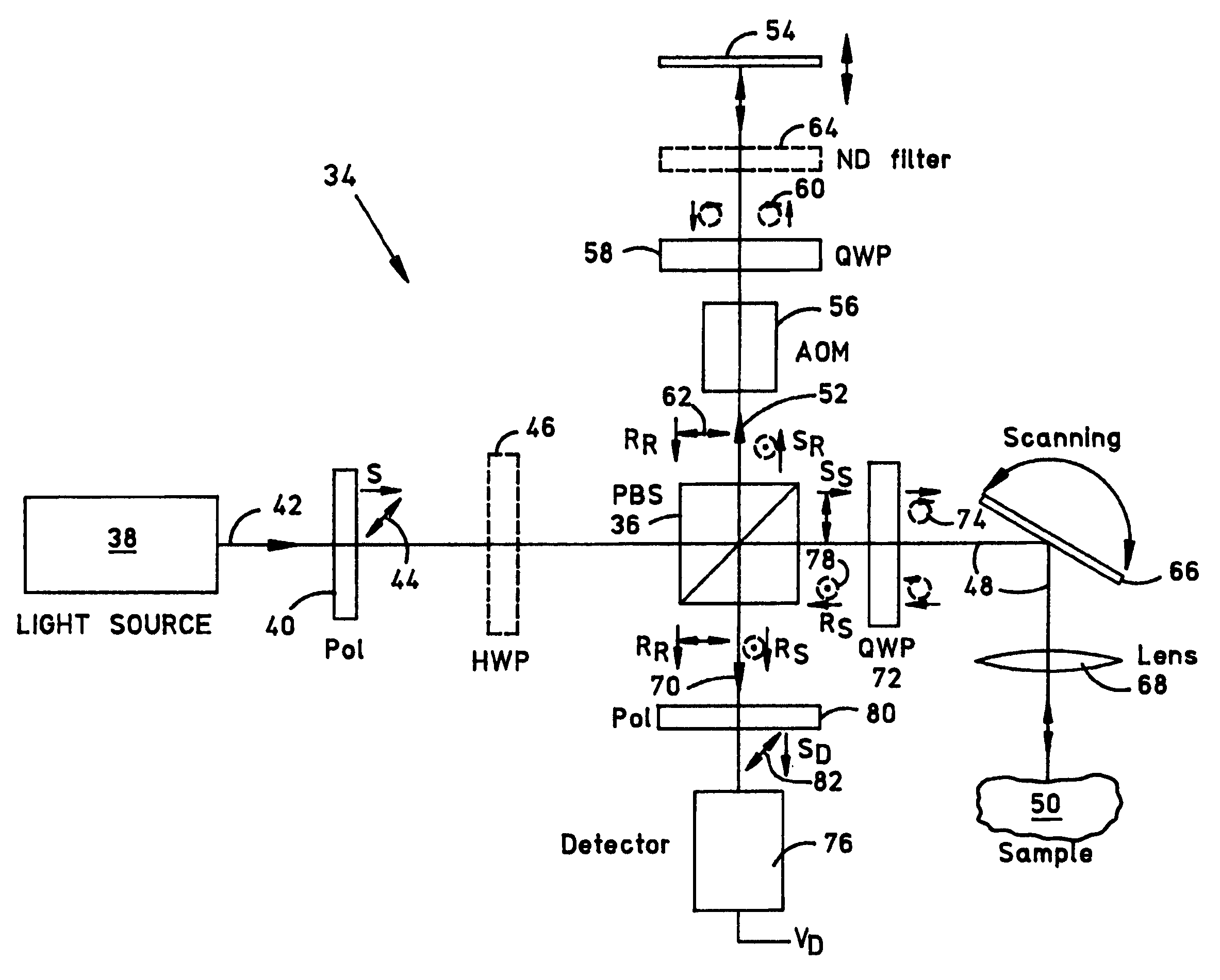
[0043]FIG. 3 is a functional block diagram illustrating a Michelson embodiment 34 of the OCT system of this invention showing one example of the signal polarization states necessary to operate the detector in a noise-optimized regime. System 34 uses the polarization properties of the optical signals to avoid wasting source power. The usual non-polarizing beam splitter of the Michelson interferometer is replaced by a polarizing beam splitter (PBS) 36, which reflects optical signals having a vertically-oriented linear polarization state and transmits optical signals having a horizontally-oriented linear polarization state. The source 38 is linearly polarized by, for example, using a polarized light emitting source (not shown) or by adding a linear polarizer 40 disposed as shown. When a partly polarized light source (e.g. one of many suitable types of super luminescent diodes) is used instead of source 38, polarizer 40 should be oriented to transmit maximum power so that both source 38...

embodiment 134

[0054]FIG. 4 is a functional block diagram illustrating a Mach-Zehnder embodiment 134 of the OCT system of FIG. 3 that may be appreciated with reference to the above description of FIG. 3, wherein the descriptive numerals for items having like functions to those disclosed in FIG. 3 are incremented by 100 so that, for example, the operation of the three PBSs 136a, 136b and 136c together may be fully appreciated with reference to the above description of PBS 36 shown in FIG. 3. The working principle of system 134 is essentially similar to that of system 34 discussed above. The function of QWP 58 in system 34 (through which pass both reference signals SR and RR) is assumed in system 134 by the HWP 158, through which passes only the reflected reference signal portion RR alone. The z-axis positioning function of reference reflector 54 is assumed by the path delay reflector 154, which is disposed to move in either direction along the z-axis as shown by the arrows. The functions of HWP 46 ...


PUM

PropertyMeasurementUnit
timeaaaaaaaaaa
wavelength rangeaaaaaaaaaa

Abstract

An optical coherence tomography (OCT) system including a polarizing splitter disposed to direct light in an interferometer such that the OCT detector operates in a noise-optimized regime. When scanning an eye, the system detector simultaneously produces a low-frequency component representing a scanning laser ophthalmoscope-like (SLO-like) image pixel and a high frequency component representing a two-dimensional (2D) OCT en face image pixel of each point. The SLO-like image is unchanging with depth, so that the pixels in each SLO-like image may be quickly realigned with the previous SLO-like image by consulting prominent image features (e.g., vessels) should lateral eye motion shift an OCT en face image during recording. Because of the pixel-to-pixel correspondence between the simultaneous OCT and SLO-like images, the OCT image pixels may be remapped on the fly according to the corresponding SLO-like image pixel remapping to create an undistorted 3D image data set for the scanned region.

Description

BACKGROUND OF THE INVENTION[0001]1. Field of the Invention[0002]This invention relates generally to optical coherence tomography (OCT) systems for three-dimensional (3D) imaging and more particularly to a power-efficient OCT system and method for rapid 3D ocular imaging without motion artifacts.[0003]2. Description of the Related Art[0004]The optical coherence tomography (OCT) art has evolved over time from the optical time-domain reflectometry (OTDR) art described by Barnoski et al. in 1976 [J. K. Barnoski, S. M. Jensen, “Fiber waveguides: A novel technique for investigation attenuation characteristics,”Appl. Opt., 15, 2112-5 (1976)]. OTDR was first employed to measure the elapsed time (t) and intensity of light reflected along a SINGLE path in optical fiber to determine the distance (d=ct) to problems along the fiber such as attenuation and breaks, making it a useful tool in optical network trouble-shooting. The original idea of OTDR consists in launching a rather short and high p...

Claims


Application Information

Patent Timeline
Patent Type & Authority Patents(United States)
IPC IPC(8): G01B11/02A61B3/12G01N21/47
CPCA61B3/102G01N21/4795
Inventor HITZENBERGER, CHRISTOPH K.
Owner CARL ZEISS MEDITEC INC
Why Eureka
Try Eureka