Optical transmission system

a transmission system and optical technology, applied in the field of optical transmission systems, can solve the problems of increasing the cost of the overall system, difficult in practice to locate the optical branching device, and expensive devices, and achieve the effect of high-quality optical transmission and prolonged transmission distan

Active Publication Date: 2006-12-05
FUJITSU LTD
View PDF9 Cites 2 Cited by
  • Summary
  • Abstract
  • Description
  • Claims
  • Application Information

AI Technical Summary

Benefits of technology

[0030]The present invention was created in view of the above circumstances, and an object thereof is to provide an optical transmission system which permits transmission distance to be prolonged without the need for repeaters, thus is economical and yet capable of high-quality optical transmission.

Problems solved by technology

Accordingly, the optical branching device 54 needs to have a high pressure-resistant structure and requires high pressure-resistant electric relays (vacuum relays etc.), and this makes the device expensive.
Also, since the branch station 53 includes the power supply device 53a, the cost of the overall system increases.
Because of the problem of geographical features of the ocean floor or cable route, however, it is very often difficult in practice to locate the optical branching device 54 near the branch station 53.
For this reason, it has been difficult up to the present to construct economical submarine optical transmission systems.
However, these techniques are focused only on efficient use of the pump light and no consideration is given to construction of systems requiring no repeaters in the branch lines.

Method used


Image

  • Optical transmission system
  • Optical transmission system
  • Optical transmission system

Examples


Embodiment Construction

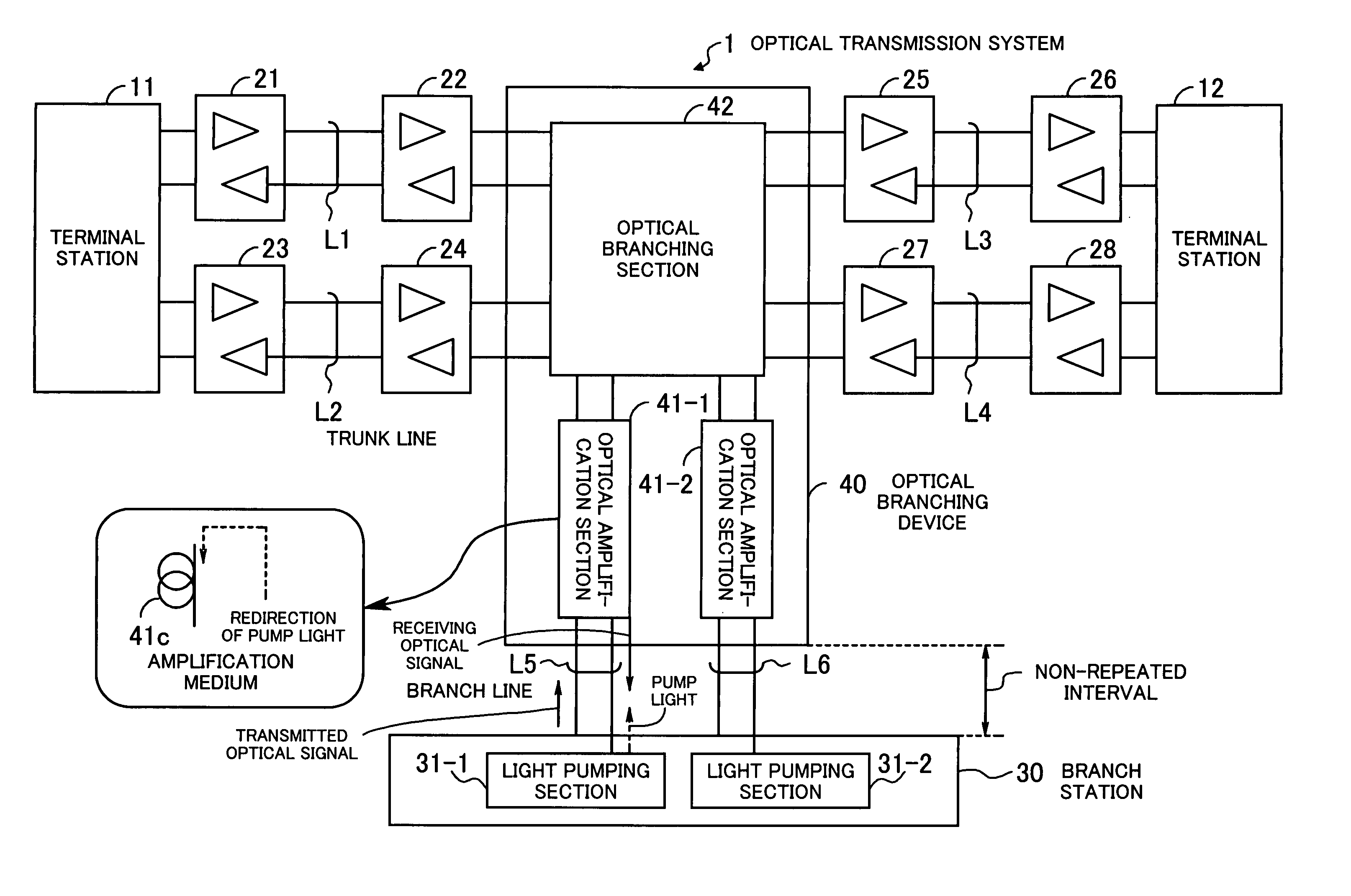
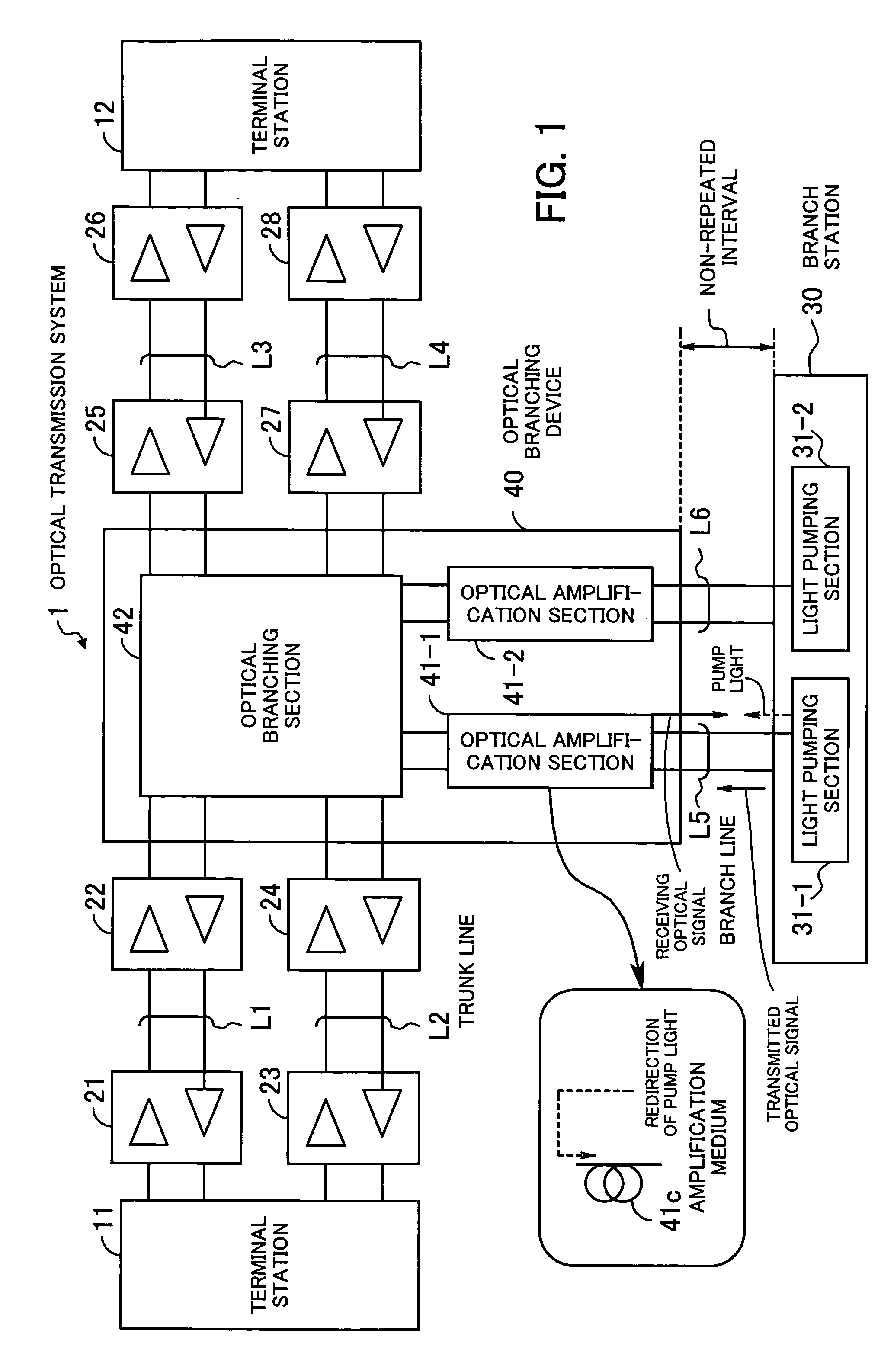
[0041]An embodiment of the present invention will be hereinafter described with reference to the drawings. FIG. 1 illustrates the principle of an optical transmission system according to the present invention. The optical transmission system 1 is a system for branching optical signals to allow the signals to be communicated among at least three stations or more and is applied, for example, to a submarine optical transmission system.

[0042]The optical transmission system 1 comprises terminal stations 11 and 12, a branch station 30, and an optical branching device 40. The terminal station 11 is connected to the optical branching device 40 by trunk lines L1 and L2, the terminal station 12 is connected to the optical branching device 40 by trunk lines L3 and L4, and the branch station 30 is connected to the optical branching device 40 by branch lines L5 and L6.

[0043]Repeaters 21 and 22 are inserted in the trunk line L1, and repeaters 23 and 24 are inserted in the trunk line L2. Repeaters...


PUM


Abstract

An optical transmission system which permits transmission distance to be prolonged without using repeaters and yet ensures economical, high-quality optical transmission. A branch station performs non-repeated communication with an optical branching point and includes a light pumping section for causing pump light to enter an optical fiber through which a branched, receiving optical signal flows, to perform optical amplification by using the fiber as an amplification medium. An optical branching device includes an optical amplification section and an optical branching section. The optical amplification section redirects the pump light originated from the branch station and propagated through a line to the paired line through which an optical signal transmitted from the branch station flows, to excite an amplification medium inserted in the paired line and doped with active material for optical amplification and thereby amplify power of the optical signal transmitted from the branch station. The optical branching section branches the optical signal transmitted from the branch station and optical signals transmitted from other stations.

Description

CROSS-REFERENCE TO RELATED APPLICATIONS[0001]This application is based upon and claims priority of Japanese Patent Application No. 2004-150061, filed on May 20, 2004, the contents being incorporated herein by reference.BACKGROUND OF THE INVENTION[0002](1) Field of the Invention[0003]The present invention relates to an optical transmission system, and more particularly, to an optical transmission system for branching optical signals to allow the optical signals to be communicated among at least three stations or more.[0004](2) Description of the Related Art[0005]In recent years, demand for international communications is rapidly increasing because of the globalization of business, the spread of the Internet, etc. Under the circumstances, submarine optical transmission systems are an important means of communication comparable to satellite communications, and expeditious realization of economical and large-capacity submarine optical transmission systems are in pressing need.[0006]A su...

Claims


Application Information

Patent Timeline
Patent Type & Authority Patents(United States)
IPC IPC(8): G02B6/26H04J14/02H04B10/00H04B10/27H04B10/29H04B10/297
CPCH04B10/2937
Inventor YOKOTA, IZUMI
Owner FUJITSU LTD
Why Eureka
Try Eureka