Method and apparatus for creating a virtual microscope slide

a virtual microscope and microscope technology, applied in the field of virtual microscope slides, can solve the problems of inability to construct an optical image sensor large enough to cover the entire image area, limited view range of pathologists, and large field of view of magnified objects, etc., and achieve the effect of reducing the number of image pixels stored and high resolution

Inactive Publication Date: 2006-12-05
OLYMPUS AMERICA
View PDF78 Cites 87 Cited by
  • Summary
  • Abstract
  • Description
  • Claims
  • Application Information

AI Technical Summary

Benefits of technology

[0015]In accordance with the present invention, there is provided a new and improved method and apparatus for constructing digitally scanned images from a microscope specimen, for storing the digitally scanned images in a tiled format convenient for viewing without a microscope, and for transferring the tiled images at multiple magnifications for viewing by another at a remote location. This is achieved by assembling together several adjacent, original microscope views at a first magnification to obtain an overall macro view of the specimen and assembling together several adjacent original microscope views at a higher magnification to create a combined data structure. The data structure may then be transferred to the remote viewer to provide this viewer multiple resolution macro and micro images of areas on the slide specimen. The data structure is constructed by digitally scanning and storing the low magnification images with their mapping coordinates and likewise, digitally scanning and storing higher magnification images with their mapping coordinates. Further, a pathologist may interactively select only those diagnostically significant areas of the specimen for digital scanning and storing to reduce significantly the number of image pixels stored at high resolution.
[0016]The data structure can be transmitted over the Internet or intranet to allow multiple users to consult on a particular microscope each using his own virtual images of the specimen. These users each may flip back and forth between different resolution images in a manner similar to that achieved when shifting among objective lens for different resolution views. However, the preferred embodiment of this invention provides a marker on the overall macro view showing the remote user where the higher resolution image is located on the specimen so that the user does not have to remember the location of the higher resolution image. Unlike the single, small optical field of view currently available, the remote user is provided with a series of abutted, tiled images each being substantially equal to one small optical field of view. Thus, the remote user is provided with better and larger macro and micro tiled images than the single, small optical fields of view taken at the same magnifications of a single tiled image.
[0017]The preferred data structure is also provided with a generic viewing program that allows the remote user to manipulate and interpret the tiled images on the. user's browser. This generic viewing program is self-contained with its own display and the interpretative program is usable with a variety of computers, browsers and monitors. The data structure uses selectively compressed data to reduce the huge amount of acquired data, e.g. 120 megabytes, into a small amount of data, e.g. 1.4 megabytes. Such smaller, more manageable amounts of data can be transmitted over a low bandwidth channel such as the Internet without the loss of resolution that would interfere with the remote pathologist's analysis. Further, the interactive program allows the pathologist to scroll and to view neighboring image areas of neighboring image tiles which were currently unavailable to the pathologist until the inventions set forth in the aforesaid application and in this application.

Problems solved by technology

Today, it is impractical to construct an optical image sensor large enough to cover the entire image area e.g., of a specimen on a microscope slide, at the required resolution.
This is because lens size and resolution / magnification issues limit the size of the field of view of magnified objects and their resulting images.
A similar problem exists on the Internet or intranet where a pathologist may receive a single field of view magnified image taken from a specimen over the Internet or the intranet on his browser.
The number of views available to the pathologist is very limited, and the pathologist is unable to select other views or to scroll to neighboring views at the areas that are most interesting to the pathologist.
While several people could see the particular digitized images being transmitted out over the Internet as they were acquired by a particular pathologist and several people could view the stored images, there was still a problem of control at operation of the microscope by each person viewing the digitized images, and a problem with acquiring and transmitting large areas of higher magnification images using the tiling method.
The photographs are difficult to use as is a video tape particularly when the user wants to move rapidly back and forth between various images and to scroll through various adjacent parts of the specimen image.
Further, current archival methods lack an overall macro image of the specimen, which allows the user to know exactly where the particular high resolution view is from when it is making an analysis of the high resolution image.
While digitized images can be stored magnetically or otherwise digitized and recorded on various recording mediums, no current archival system allows the user to toggle back and forth between high magnification images and low magnification images or between various images at different magnifications such as that achieved by a pathologist switching microscope objective lenses in real time to get the macro and micro images from the same location on the specimen.
Heretofore, the practice of pathology has been relatively limited to the use of microscopes and to the pathologist having to use the microscope to review the particular specimen.
One of the first problems is how to seam together neighboring tile images to form a seamless overall view of these tiles.
Heretofore, attempts to seam the tiles used software to combine the pixels at the tile boundaries and have been generally unsuccessful.
Another problem is that of mapping of coordinates beginning with the coordinates, usually X and Y coordinates, from and at the microscope stage carrying the slide and then the mapping of coordinates on the scanning screen not only for one magnification but also to coordinate the mapping for the respective multiple resolution images taken typically at 1.25×, 10× and 40× or more.
Another problem with acquiring image tiles and sending them over a low bandwidth Internet channel is that both the storage requirements on the server and the amount of data acquired per slide become high, such as for example, 120 megabytes to one gigabyte.
Even with this selective interaction by a pathologist in constructing the macro and micro digitized images with a vastly reduced amount of image tiles relative to that which would be acquired if the entire specimen where imaged at each of the multiple magnifications, the acquired amount of data is a monstrous problem of transmitting in a reasonable amount of time over a narrow bandwidth channel to an ordinary web browser having limited storage capacity.
While rough compression techniques could be used, they cannot be used at the expense of providing the high resolution image that the pathologist must have for diagnosis of the specimen.

Method used


Image

  • Method and apparatus for creating a virtual microscope slide
  • Method and apparatus for creating a virtual microscope slide
  • Method and apparatus for creating a virtual microscope slide

Examples


Embodiment Construction

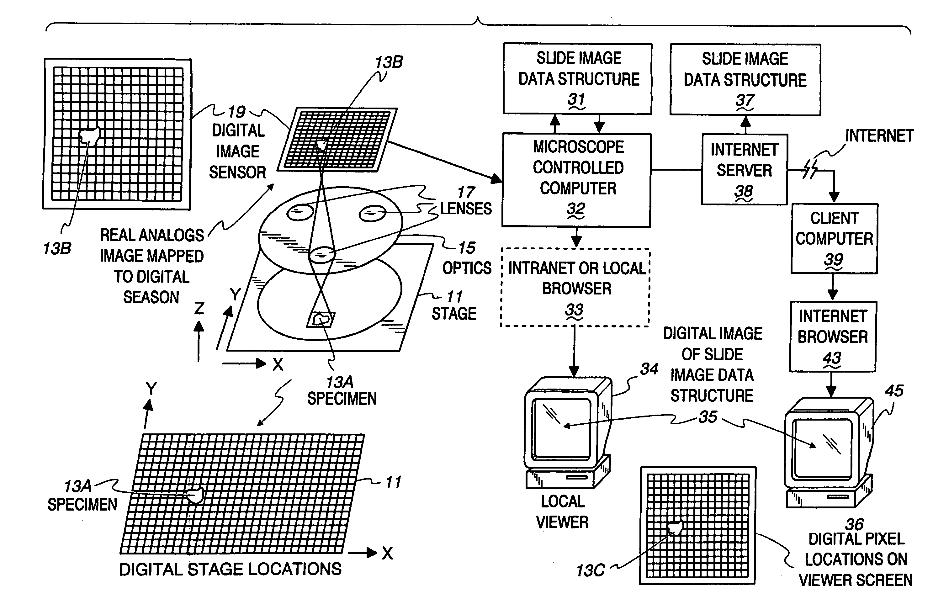
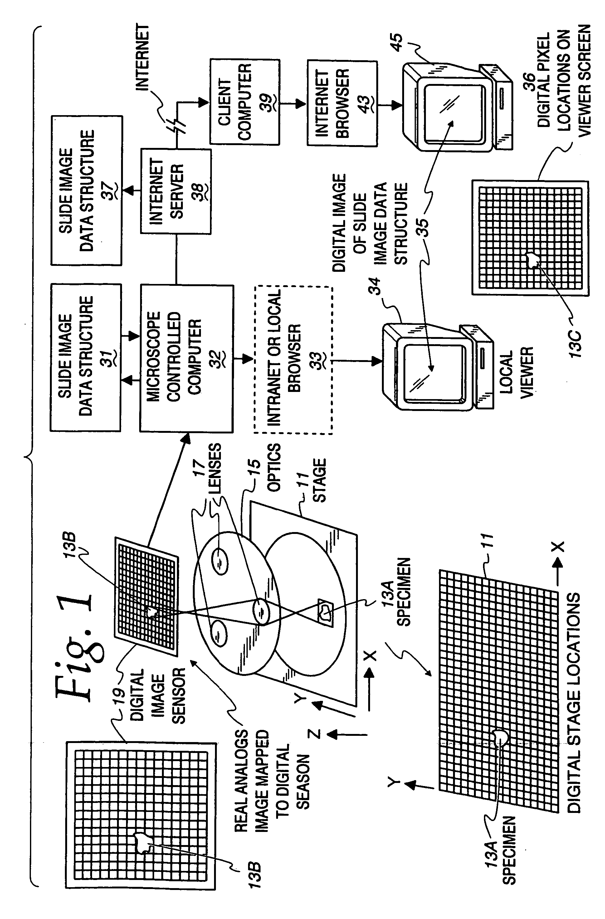
[0061]FIG. 1 is a block diagram of a system according to the invention for creating, and transmitting over an intranet or via the Internet a virtual microscope slide, i.e. interrelated data structures and display procedures depicting at multiple resolutions, images of a specimen on a microscope slide. The system includes a microscope with a digital platform for supporting the microscope slide. Digital platform or stage 11 has been specially calibrated to include a large number of increments for locating portions of specimen images with high precision. After calibration and initial registration of stage 11 in the microscope setup, a microscope slide or other substrate with a specimen to be scanned is placed on stage 11.

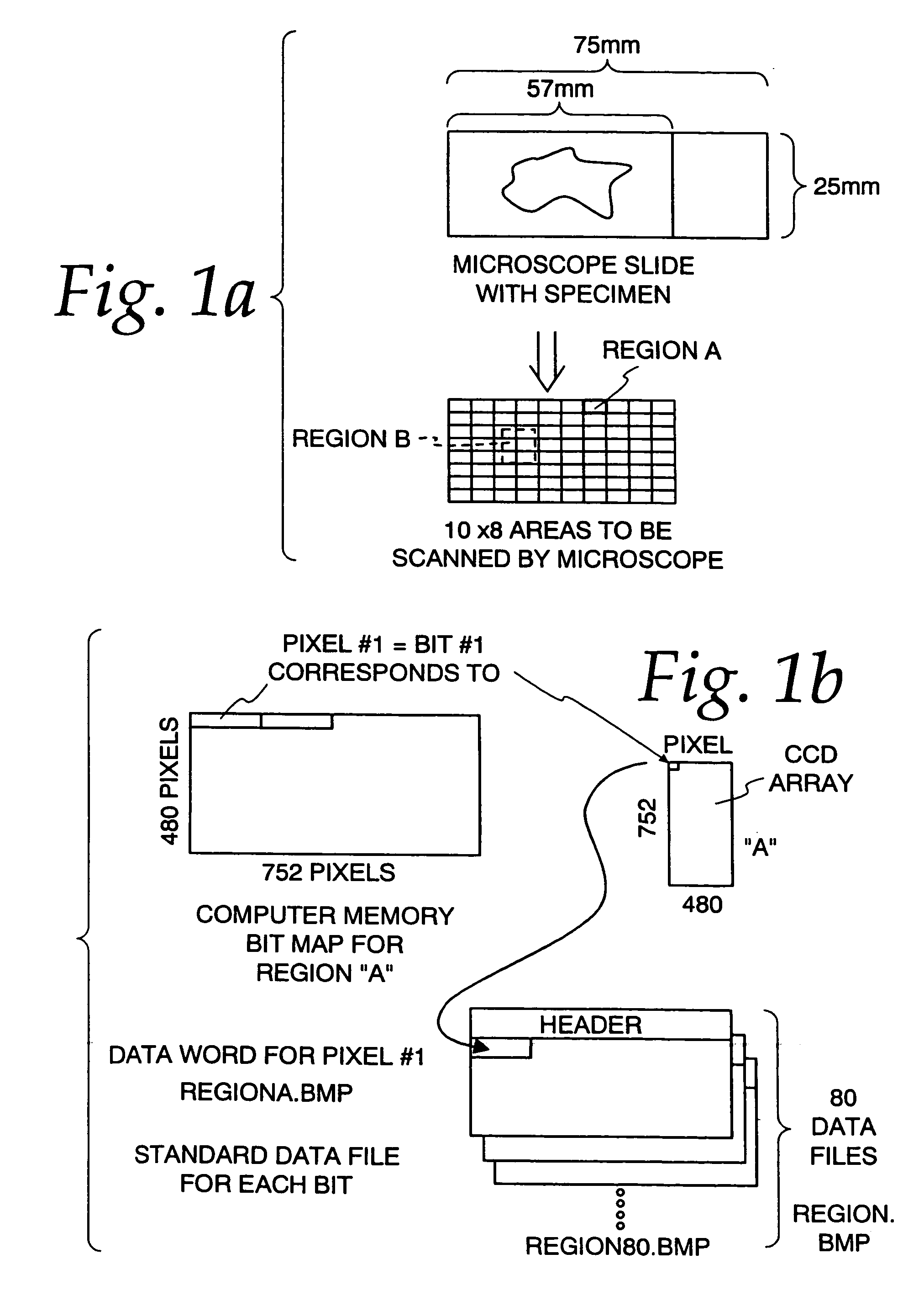
[0062]For exemplary purposes, the creation of virtual microscope slide specimen according to the invention will be described with respect to a breast cancer specimen. The first step in creating a data structure according to the invention is to establish a macro image o...


PUM

PropertyMeasurementUnit
compression ratiosaaaaaaaaaa
data structureaaaaaaaaaa
areaaaaaaaaaaa

Abstract

A method and apparatus are disclosed for making and using a virtual microscope slide data structure having data for an overall image of the specimen or a substantial portion thereof along with data for higher magnification images of selected areas within the overall image and along with data useable for correlating, linking and / or coherently assembling low magnification, overall image segments with the higher image segments. This latter data may comprise a control program for manipulating images to allow zooming different, higher magnification images into view, scrolling adjacent high magnification images into view or marking the location of a displayed higher magnification view on the overall image to assist in navigation by a viewer to locate and quickly display suspicious areas within the specimen. The data structure may be sent over the Internet.

Description

FIELD OF THE INVENTION[0001]This patent application is a continuation patent application of patent application Ser. No. 10 / 365,548, filed on Feb. 12, 2003, now U.S. Pat. No. 6,775,402 which is a continuation patent application of patent application Ser. No. 09 / 574,423, filed on May 19, 2000, now U.S. Pat. No. 6,522,774, which is a continuation of patent application Ser. No. 09 / 032,514, filed on Feb. 27, 1998, now U.S. Pat. No. 6,272,235, which is a continuation-in-part of patent application Ser. No. 08 / 805,856, filed on Mar. 3, 1997, now U.S. Pat. No. 6,101,265.BACKGROUND OF THE INVENTION[0002]The invention described in the aforesaid application answers a need, a requirement to image and digitally record an object in a relatively flat plane at high resolution / magnification. Today, it is impractical to construct an optical image sensor large enough to cover the entire image area e.g., of a specimen on a microscope slide, at the required resolution. This is because lens size and resol...

Claims


Application Information

Patent Timeline
Patent Type & Authority Patents(United States)
IPC IPC(8): G06F17/00G06F7/00G02B21/36G01N15/14G02B21/00G06F19/00G06K9/00G06T1/00G06T3/40H04N7/18
CPCG01N15/1475G02B21/367G06F19/321G06F19/3406G06F19/366G06K9/00127G06T3/4038G06F19/3418Y10S707/99943Y10S707/99945Y10S707/99942G16H40/63G16H10/40G16H40/60G16H30/20G06V20/69
Inventor BACUS, JAMES W.BACUS, JAMES V.
Owner OLYMPUS AMERICA
Why Eureka
Try Eureka