Closing cylinder

a technology of closing cylinders and cylinders, which is applied in the direction of limiting/preventing/returning the movement of parts, lock casings, keyhole guards, etc., and can solve the problem of affecting the factor of relative high inventory costs

Inactive Publication Date: 2006-12-12
RAMSAUER DIETER
View PDF35 Cites 8 Cited by
  • Summary
  • Abstract
  • Description
  • Claims
  • Application Information

AI Technical Summary

Benefits of technology

[0007]The object is met in that the drive for a bolt or closure or the like is held at the end of the closing core in a positive engagement so as to be exchangeable. Accordingly, it is not necessary to stock various versions of the closing core in its entirety; rather, only different drives for bolts or closures that can be connected to the unchangeable closing cores must be stocked depending on the intended object. This lowers costs and also reduces the space requirement for a larger inventory.
[0010]In particular, this prevents difficulties during assembly or operation caused by separation of the tounge and groove during assembly.
[0011]For reasons of stability, it is advantageous when the tounge proceeds from a circular disk which contacts the end face of the closing core when the tongue is inserted into the groove.

Problems solved by technology

It is disadvantageous in this prior art that a different cylinder core is required depending on the intended purpose, which means that relatively high inventory costs must be factored in.

Method used


Image

  • Closing cylinder
  • Closing cylinder
  • Closing cylinder

Examples


Embodiment Construction

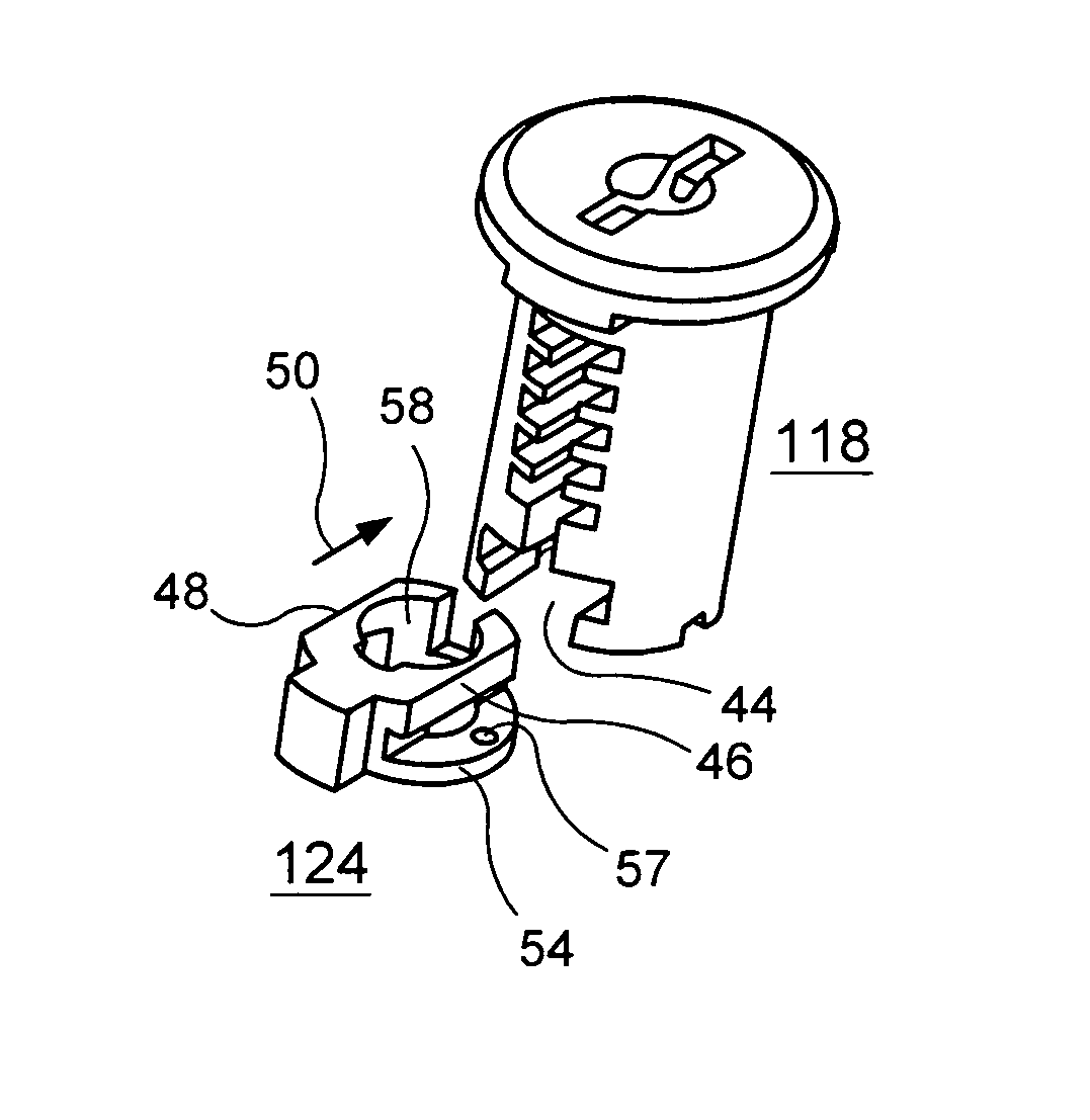
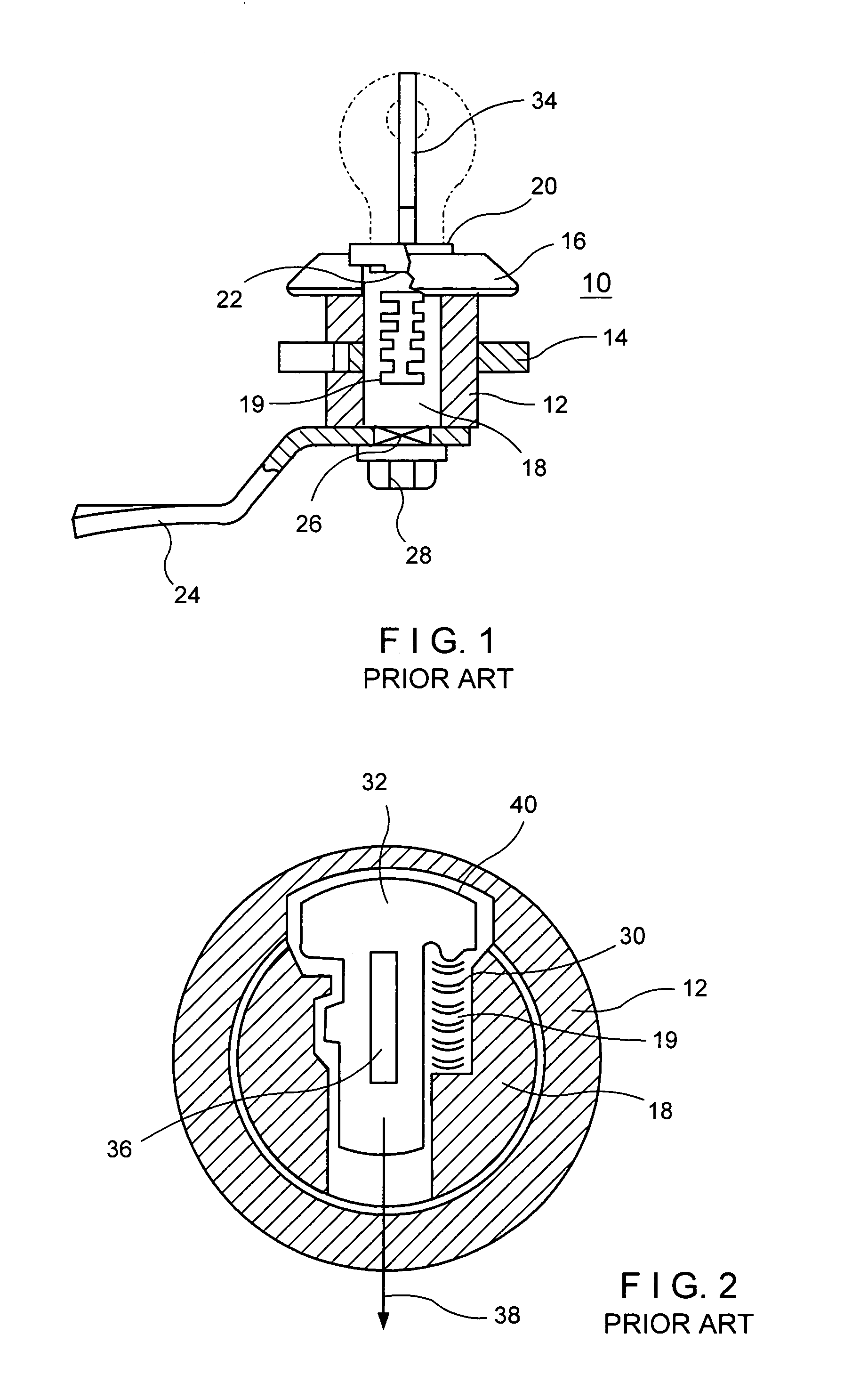
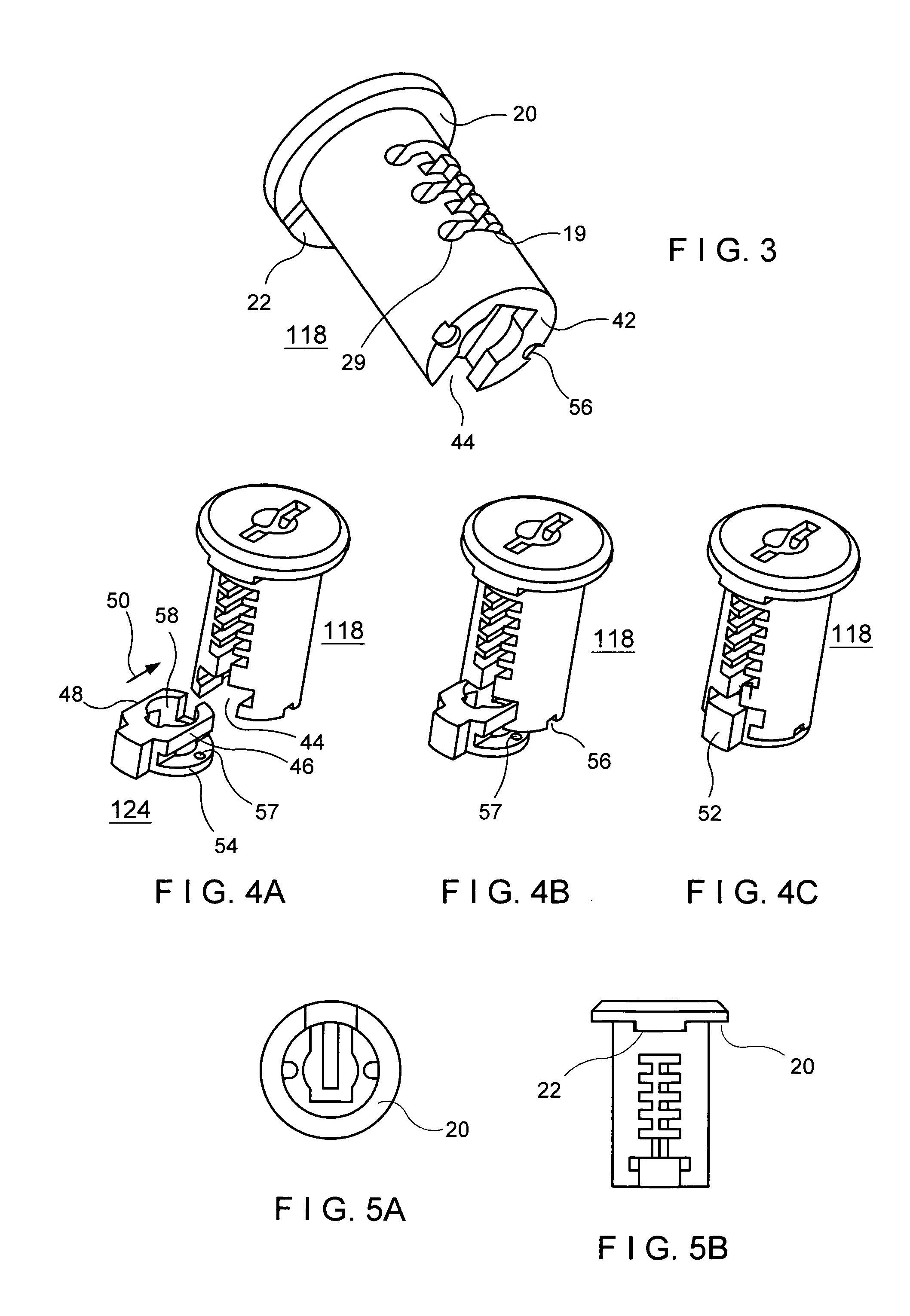
[0041]FIG. 1 is a side view in partial axial section showing a closing cylinder 10 for closure devices, in this case a sash closure, comprising a cylindrical closing housing 12 which can be received so as to be fixed in an opening formed by a handle, closure device or the like, for example, in this case, in a switch cabinet door, wherein, for example, the door leaf is clamped between a key catch 16, formed by the housing 12, and a union nut 14 by tightening the nut. A closing core 18 is rotatably mounted in the closing housing 12. At one of its ends, the closing core 18 is axially supported by an edge projection 20, which is usually contoured, on the housing edge in the case of FIG. 1 in a countersink formed by the key catch 16. The contoured edge projection, e.g., in the form of a nose 22, and the housing edge form means for limiting the rotational path of the core 18 inside the housing 12. At the opposite end, the core forms a drive for a bolt 24 or some other closure, not shown. ...


PUM


Abstract

The description relates to a closing cylinder for closure devices comprising a cylindrical closing housing which can be received in a fixed manner in an opening formed by a handle, closure device or the like, a closing core (18) is rotatably mounted in this closing housing and is axially supported at one of its ends on the housing edge by an edge projection (20) and carries or forms a drive at its other end for a bolt or closure (124), wherein, according to the invention, the drive (124) is held at the end of the closing core (118) in a positive engagement so as to be exchangeable.

Description

CROSS-REFERENCE TO RELATED APPLICATIONS [0001]This application claims priority of International Application No. PDT / EP01 / 10969, filed Sep. 22, 2001 German Application No. 200 18 281.1, filed Oct. 25, 2000, the complete disclosures of which are hereby incorporated by reference.BACKGROUND OF THE INVENTION[0002]a) Field of the Invention[0003]The invention is directed to a closing cylinder for closure devices comprising a cylindrical closing housing which can be received in a fixed manner in an opening formed by a handle, closure device or the like. A closing core is rotatably mounted in this closing housing and is axially supported at one of its ends on the edge of the closing housing by an edge projection. The edge projection and the housing edge can form means for limiting the rotational path of the closing core inside the housing, and the closing core carries or forms a drive at its other end for a bolt or closure.[0004]b) Brief Description of the Related Art[0005]A closing cylinder...

Claims


Application Information

Patent Timeline
Patent Type & Authority Patents(United States)
IPC IPC(8): E05B17/04E05B13/10E05B15/16E05B63/00E05C3/04
CPCE05B17/04E05B13/10E05B15/1635E05B63/0056E05C3/042Y10T70/7661Y10T70/7706Y10T70/5761Y10T70/7638Y10T70/577Y10T70/7684
Inventor RAMSAUER, DIETER
Owner RAMSAUER DIETER
Why Eureka
Try Eureka