
Housing for an optical reader

Active Publication Date: 2006-12-12
HAND HELD PRODS
View PDF67 Cites 40 Cited by
  • Summary
  • Abstract
  • Description
  • Claims
  • Application Information

AI Technical Summary

Benefits of technology

[0015]Briefly, in accordance with one aspect of the invention, the front face of an optical reader is angled backwardly from a plane that is normal to the optical axis of the device, thereby improving the visibility of the target to the operator as the scan is being made at close distances.
[0017]By yet another aspect of the invention, a central portion of the front face of an optical scanner is recessed to improve the visibility of the target to the operator as the scanner face is brought into close proximity to the target.
[0018]In accordance with yet another aspect of the invention, the position of on the front face window of an optical reading device is substantially offset inwardly to protect the window from damage that might otherwise occur.

Problems solved by technology

With existing optical readers, the operators view is generally obstructed when the reader is brought into close proximity to the code.
Another problem associated with optical readers is the tendency of the window to become scratched because of its prominent position at the front face of the reader.
Damage can occur to the window during the normal course of scanning as the window comes in contact with the product being scanned, or it can occur during periods of non-use when the scanner is simply at rest on the counter, for example.
In any case, any such scuffing or scratching damage to the window may cause for less reliable or improper readings and may necessitate the replacement of the window.
Another thing that maybe affect the reliability and durability of the reader is the shock that may occur from repeatedly setting it down on the counter and / or dropping it from time to time.
Although the casings are generally made from a material that is durable enough to withstand the dropping of a unit on a hard surface, the sensitive internal components, and even the outer casing, may be damaged by such treatment.

Method used


Image

  • Housing for an optical reader
  • Housing for an optical reader
  • Housing for an optical reader

Examples


Embodiment Construction

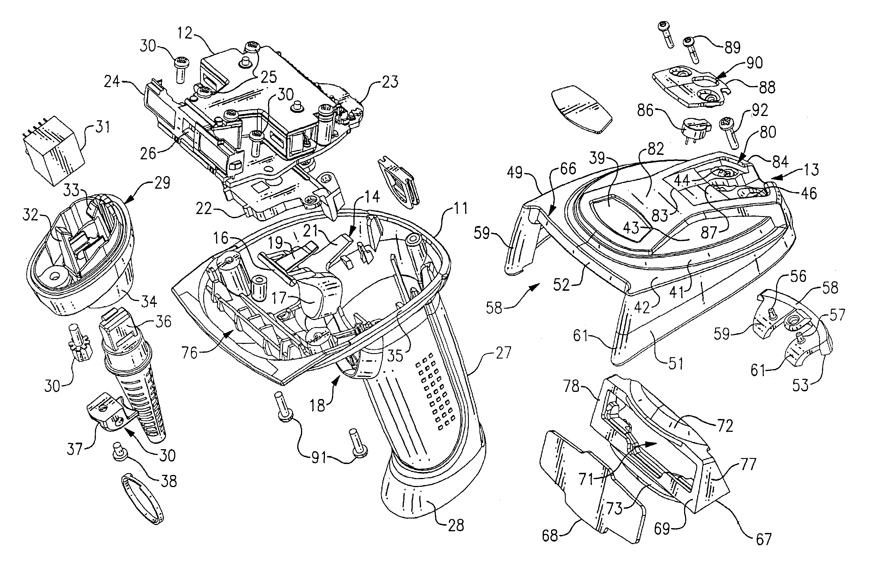
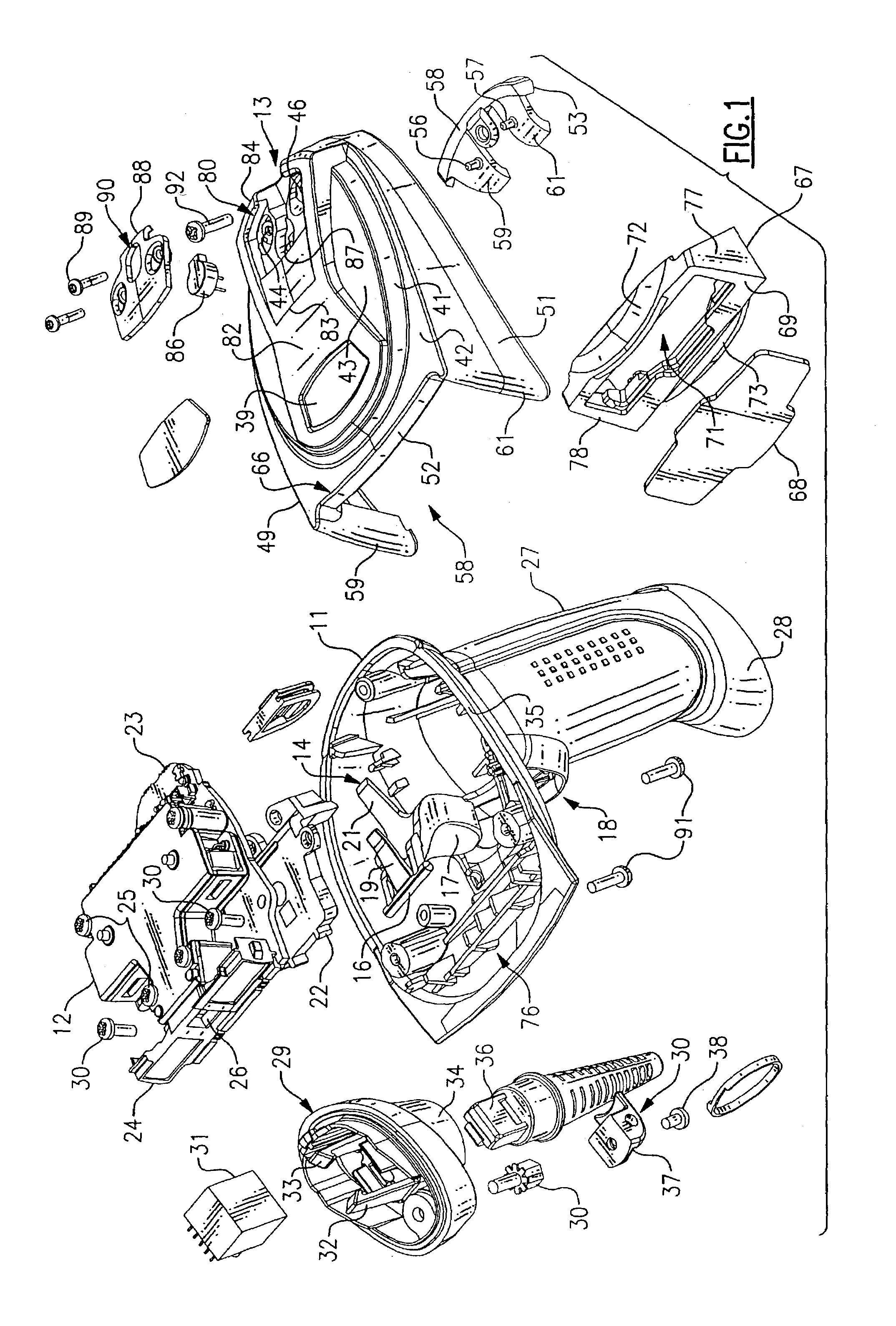
[0029]FIG. 1, shows the various components of the optical reader device, including a handle assembly 11, an optics assembly 12 and a housing cover 13.

[0030]Contained within an internal cavity 14 of the handle assembly 11, is a trigger assembly 16 with it's trigger 17 loosely extending through a trigger opening 18 such that the trigger 17 can be selectively depressed by the operator. On the upper side of the trigger assembly 16 is a pair of contact members 19 and 21 which, when the trigger is depressed, engage surfaces on the trigger frame 22 mounted thereabove. Disposed immediately above and attached to the trigger frame 22 is a printed circuit board 23 to which the optical assembly 12 is mounted.

[0031]The optical assembly 12 has mounted therein a plurality of light emitting diodes which project light forwardly through a lens assembly 24 for the illumination of a target such as a bar code. An optics assembly within the lens assembly 24 then projects an image back through an opening ...


PUM


Abstract

A body portion of an optical reader has an elastomeric skirt surrounding the lateral edges thereof. The laterally spaced front edges of the skirt, which are on either side of a window through which the light is emitted and received along an optical axis, are angled rearwardly from a plane normal to the axis. The front edges extend downwardly and forwardly from a front edge of the bottom wall of a body, and also extend forwardly from a front edge of the top wall of the body. These features allow the lower ends of the front edges of the skirt to be placed on a surface near the target to act as a fulcrum in rotating the handle of the scanner to selectively place the reader in close proximity to the target, while at the same time allowing the operator to view the target. An elastomeric collar is applied to the lower end of the handle such that when the scanning device is placed at rest in an unused condition, no matter what the rotational position with respect to the axis of the handle, the device will be supported at one elastomeric covered position on each of the handle and the skirt. Other features of the scanning device provide for a stable parking of the scanner when not in use and a substantial recessing of the front window to thereby protect it from contact with objects that may tend to scratch or damage the window.

Description

CROSS REFERENCE TO RELATED APPLICATIONS[0001]This application is related to the applications enumerated below, all of which are being filed with the United States Patent and Trademark Office contemporaneously herewith on Jan. 9, 2003 by Express Mail, and all of which are subject to assignment to the same assignee of this application, the disclosure of each of which is incorporated herein by reference in its entirety: “Optical Reader System Comprising Digital Circuit” assigned U.S. patent application Ser. No. 10 / 339,424 (Abandoned), entitled “Analog-to-Digital Converter with Automatic Range and Sensitivity Adjustment” assigned U.S. patent application Ser. No. 10 / 339,004 (Abandoned), entitled “Decoder Board for an Optical Reader Utilizing a Plurality of Imaging Modules” assigned U. S. patent application Ser. No. 10 / 339,439 (Pending), entitled “Manufacturing Methods for a Decoder Board for an Optical Reader Utilizing a Plurality of Imaging Formats” assigned U.S. patent application Ser....

Claims


Application Information

Patent Timeline
IPC IPC(8): G06K7/10
CPCG06K7/10881
Inventor FITCH, TIMOTHY R.BECKHUSEN, GERARD F.COLEMAN, ERICIZZO, JOHN C.RAMSEY-MACOMBER, LARRYROBERTS, CLAYTON
Owner HAND HELD PRODS
Features
  • Generate Ideas
  • Intellectual Property
  • Life Sciences
  • Materials
  • Tech Scout
  • Unparalleled Data Quality
  • Higher Quality Content
  • 60% Fewer Hallucinations
Learn More