Projection system with scrolling color illumination

a projection system and color illumination technology, applied in the field of optical systems, can solve the problems of reducing wasting two-thirds of light, and reducing the efficiency of single panel system, so as to reduce the angular separation

Inactive Publication Date: 2006-12-12
3M INNOVATIVE PROPERTIES CO
View PDF33 Cites 40 Cited by
  • Summary
  • Abstract
  • Description
  • Claims
  • Application Information

AI Technical Summary

Benefits of technology

[0006]Another exemplary embodiment of the present disclosure is directed to a method of illuminating an imager panel that includes passing light beams of different color bands along respectively different paths to a rotating prism; and transmitting the light beams of the different color bands through the rotating prism. The transmitted light beams in the different color bands are reflected through different angles so as to reduce angular separations between light beams of the different color bands. The imager panel is illuminated with the reflected light beams.

Problems solved by technology

The use of such a filter, however, generally results in about two-thirds of the light being discarded at any one time, since the lamp supplies white light but the imager panel is illuminated with only one color.
Thus, single panel systems suffer from reduced efficiency.
Three panel systems, on the other hand, are much more complex, require precise alignment among all the imager panels, and are more expensive due to the larger parts inventory.

Method used


Image

  • Projection system with scrolling color illumination
  • Projection system with scrolling color illumination
  • Projection system with scrolling color illumination

Examples


Embodiment Construction

[0022]The present invention is applicable to projection systems and is more particularly applicable to single panel projection systems that employ a scrolling prism for scrolling areas of different color on an imager panel.

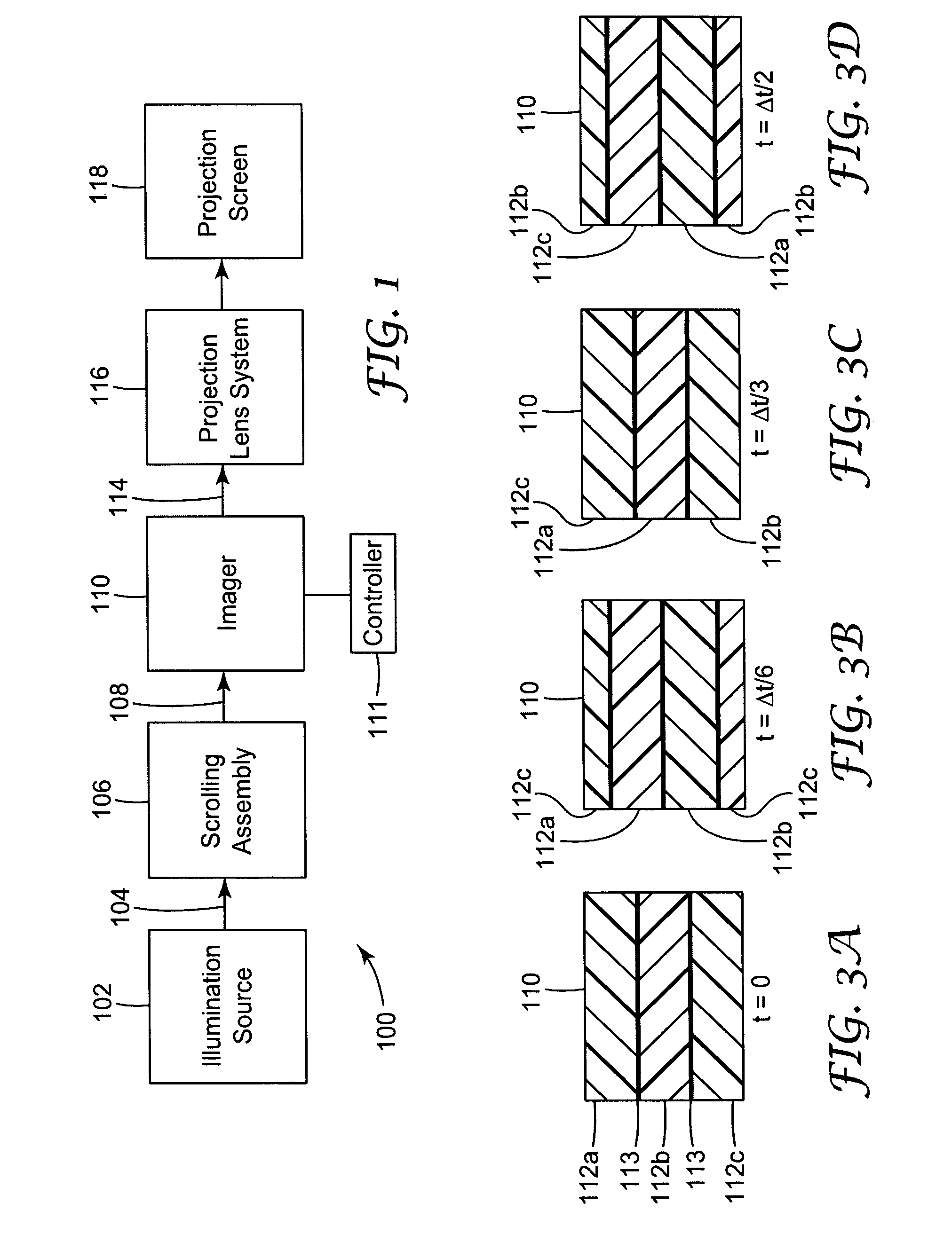
[0023]One type of projection system according to the present disclosure uses a single imager panel illuminated with non-overlapping areas of light in different color bands. A schematic block representation of such a projection system 100 is presented in FIG. 1, in which an illumination source 102 generates light 104 that passes into a scrolling assembly 106. Scrolled light 108 from the scrolling assembly 106 is directed on to the imager panel 110. The image displayed by the imager panel 110 is controlled by a controller 111, for example a microprocessor or the like. The scrolled light 108 includes two or more areas of light in different color bands (shown in FIGS. 3A–3D), for example areas 112a–112c, which may be red, green and blue color bands. Image light 114 fr...


PUM


Abstract

A projection system having an imager panel uses a scrolling prism assembly to illuminate different portions of the imager panel with light of different color simultaneously. The scrolling prism assembly can split light from a white light source into two or more different color bands that propagate through the scrolling prism in different directions, and it can reflectively combine the light so that the different color bands pass out of the scrolling prism assembly parallel. The scrolling prism assembly can also compensate for chromatic aberrations in the light received from the light source.

Description

FIELD OF THE INVENTION[0001]The invention relates to optical systems, and more particularly to projection display systems as might be used, for example, in projection televisions and the like.BACKGROUND[0002]Some optical imaging systems include a transmissive or a reflective imager panel, also referred to as a light valve or light valve array, which imposes an image on a light beam. Transmissive light valves are typically translucent and allow light to pass through. Reflective light valves, on the other hand, reflect only selected portions of the input beam to form an image. Reflective light valves provide important advantages, as controlling circuitry may be placed behind the reflective surface and more advanced integrated circuit technology becomes available when the substrate materials are not limited by their opaqueness. New potentially inexpensive and compact liquid crystal display (LCD) and digital light processor (DLP) projector configurations are becoming possible through th...

Claims


Application Information

Patent Timeline
Patent Type & Authority Patents(United States)
IPC IPC(8): G03B21/14H04N9/31
CPCH04N9/3117H04N9/3197
Inventor CONNER, ARLIE R.
Owner 3M INNOVATIVE PROPERTIES CO
Why Eureka
Try Eureka