Folded back portion flattening device, sheet processor, and image forming apparatus

a flattening device and back portion technology, applied in the direction of electrographic process, paper/cardboard containers, instruments, etc., can solve the problems of unstable, inability to easily convey or store, and prone to falling apart, so as to reduce the load

Active Publication Date: 2006-12-12
CANON KK
View PDF10 Cites 49 Cited by
  • Summary
  • Abstract
  • Description
  • Claims
  • Application Information

AI Technical Summary

Benefits of technology

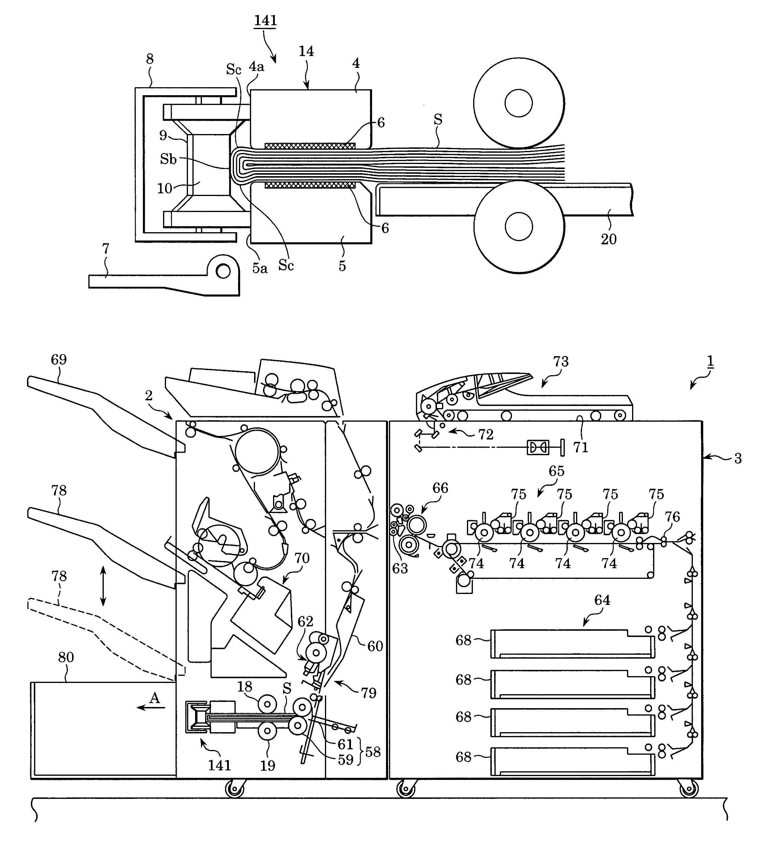
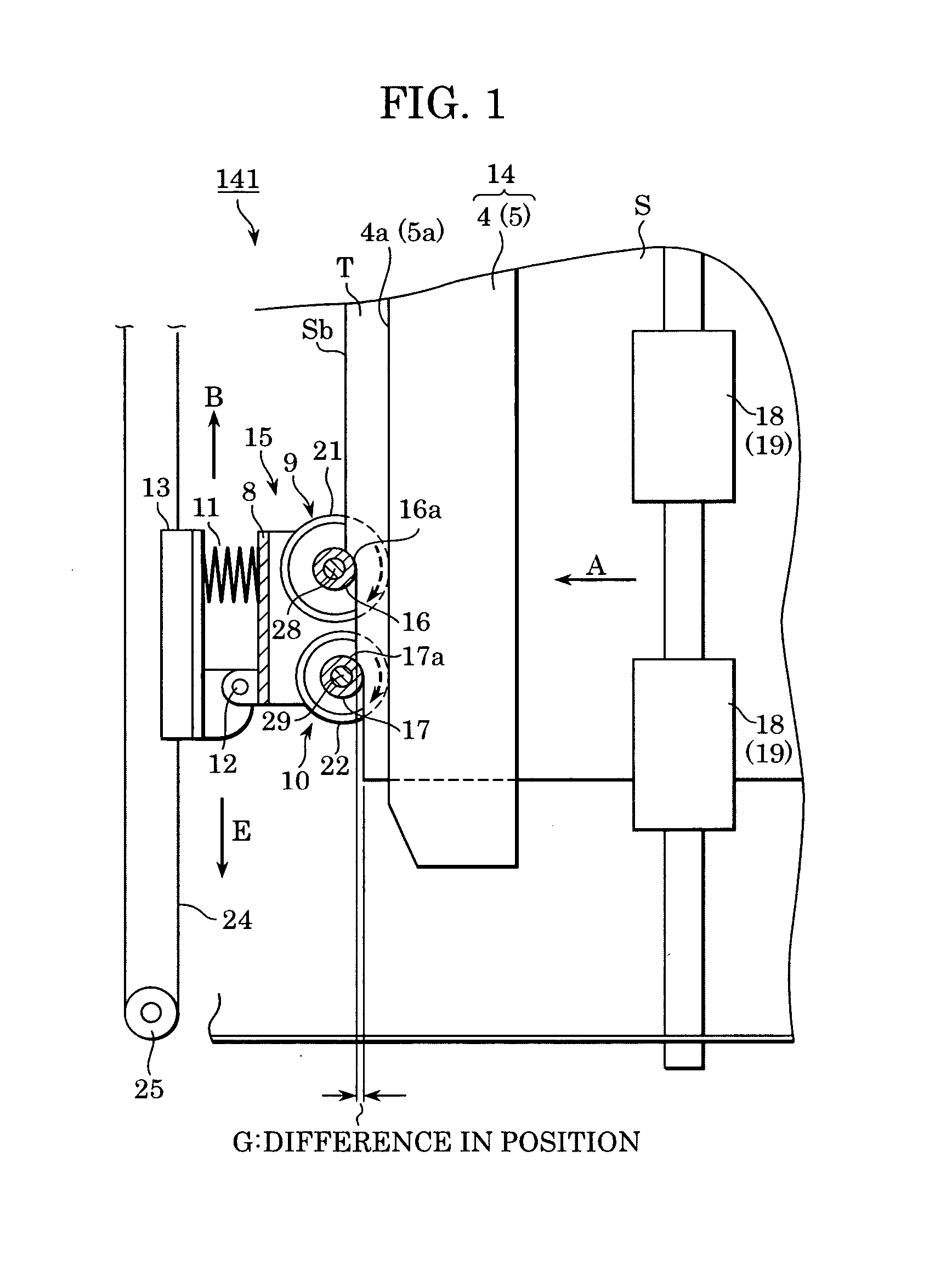
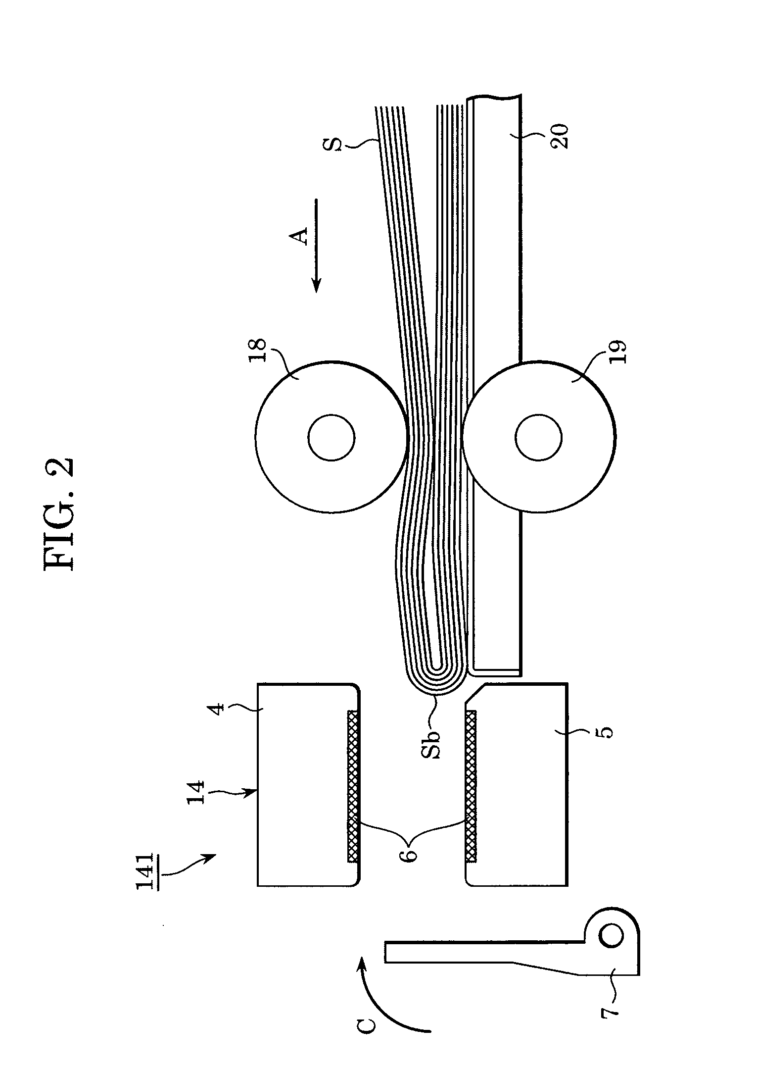
[0014]The present invention is directed to a folded back portion flattening device which can reduce a load that is produced when a pressing member starts to press a folded back portion of a sheet bundle in a pressing unit which flattens the folded back portion of the sheet bundle.
[0015]The present invention is also directed to a sheet processor which provides increased sheet processing efficiency as a result of incorporating the folded back portion flattening device which can reduce a load that is produced when the pressing member of the pressing unit starts to press a folded back portion of a sheet bundle.
[0016]The present invention is further directed to an image forming apparatus which provides increased image formation efficiency as a result of incorporating the sheet processor which provides increased sheet processing efficiency.
[0020]Since the folded back portion flattening device of the present invention includes a plurality of pressing members so that the pressing surface of the second pressing member, which presses the folded back portion after the pressing surface of the first pressing member has pressed the folded back portion, presses deeper into an edge of the sheet bundle than the pressing surface of the first pressing member, the folded back portion can be gradually pressed successively by the pressing members. Therefore, the load that is produced when any pressing member starts pressing the folded back portion is reduced, so that the folded back portion is easily flattened.
[0021]The sheet processor of the present invention includes the folded back portion flattening device which can easily flatten a folded back portion of a sheet bundle. Therefore, sheet processing efficiency is increased. In addition, sheet bundles are conveyed to the folded back portion flattening device at an interval that is not larger than necessary, thereby resulting in increased sheet processing efficiency.
[0022]The image forming apparatus of the present invention includes the sheet processor having increased sheet processing efficiency. Therefore, sheet bundles can be conveyed to the sheet processor at an interval that is not larger than necessary, thereby resulting in increased image formation efficiency.

Problems solved by technology

When such folded sheet bundles are stacked, they become unstable.
Therefore, they tend to fall apart, as a result of which they cannot be easily conveyed or stored when stacked.
Consequently, it is difficult to flatten the folded back portion Sb.
Therefore, sheet processing efficiency is poor.
In addition, it is necessary to convey bundles of sheets to the flattening device at an interval that is larger than necessary, thereby resulting in poor sheet processing efficiency.
Further, in the image forming apparatus having the sheet processor having a poor sheet processing efficiency, it is necessary to convey sheets to the sheet processor at an interval that is larger than necessary, thereby resulting in poor image formation efficiency.

Method used


Image

  • Folded back portion flattening device, sheet processor, and image forming apparatus
  • Folded back portion flattening device, sheet processor, and image forming apparatus
  • Folded back portion flattening device, sheet processor, and image forming apparatus

Examples


third embodiment

Folded Back Portion Flattening Device of the Third Embodiment

Structure of the Folded Back Portion Flattening Device of the Third Embodiment

[0092]As shown in FIGS. 11 and 12, a folded back portion flattening device 341 of the third embodiment is constructed by providing the first pressing rollers 9 of the folded back portion flattening devices 141 and 241 of the first and second embodiments with the function of guiding a folded back portion of a sheet bundle. Parts of the folded back portion flattening device 341 corresponding to those of the folded back portion flattening device 141 of the first embodiment are given the same reference numerals and will not be described below.

[0093]FIG. 11 shows a first pressing roller 309 and a second pressing roller 10 of the folded back portion flattening device 341 as seen from the folded back portion of the sheet bundle. Tapering portions 331, which serve as guide surfaces, are formed on and under (in FIG. 11) a pressing roller portion 316 havin...


PUM

PropertyMeasurementUnit
diametersaaaaaaaaaa
diameteraaaaaaaaaa
resilientaaaaaaaaaa

Abstract

A folded back portion flattening device includes a gripper and a presser. The gripper grips a sheet bundle formed into a booklet with the folded back portion protruding from the gripper. The presser presses the folded back portion of the sheet bundle gripped by the gripper, and includes pressing rollers which have pressing rotational surfaces and which are disposed along the folded back portion. The pressing rotational surfaces press the folded back portion. The pressing rollers are disposed so that the rotational pressing surface of a second pressing roller, which presses the folded back portion after the rotational pressing surface of a first pressing roller has pressed the folded back portion, presses deeper into an edge of the sheet bundle than the rotational pressing surface of the first pressing roller. At least one of the gripper and presser is movable in a direction parallel to the folded back portion.

Description

CROSS-REFERENCE TO RELATED APPLICATIONS[0001]This application is related to U.S. patent application Ser. No. 11 / 066,131, entitled “Sheet Processing Device And Image formation Apparatus”, filed Feb. 24, 2005, and to U.S. patent application Ser. No. 11 / 065,325, entitled “Sheet Processor and Image-Forming Apparatus”, filed Feb. 24, 2005, which are incorporated in their entirety by reference herein.BACKGROUND OF THE INVENTION[0002]1. Field of the Invention[0003]The present invention relates to a folded back portion flattening device which flattens a folded back portion of a bundle of sheets, a sheet processor incorporating the folded back portion flattening device, and an image forming apparatus. More particularly, the present invention relates to a folded back portion flattening device capable of reducing a load that is produced when a pressing roller starts pressing a folded back portion of a bundle of sheets, a sheet processor, and an image forming apparatus.[0004]2. Description of t...

Claims


Application Information

Patent Timeline
Patent Type & Authority Patents(United States)
IPC IPC(8): B31B1/26B42C5/02B42B2/00B42C5/00B42C19/00B65H29/12B65H37/00B65H45/04G03G15/00
CPCB65H29/12B65H37/00B65H45/18B65H2301/51232B65H2701/13212
Inventor FUJIMOTO, HITOSHIOBUCHI, YUSUKEKAMIYA, DAISAKUWATANABE, KIYOSHINAKAMURA, TOMOKAZUHAYASHI, KENICHISUZUKI, TOSHIMASAKUSHIDA, HIDEKIOIKAWA, ATSUTERU
Owner CANON KK
Why Eureka
Try Eureka