
Apparatus for delivery of ocular implants

a technology for ocular implants and apparatus, which is applied in the field of apparatus and methods, can solve the problems of inability to introduce drugs or therapeutic agents into the eye and maintain these drugs, increase the incidence of unacceptable side effects of drugs, and inability to simply ocular instillation or application is not an acceptable alternative, so as to enhance the ability of the wound to seal, and reduce the amount of leakage

Inactive Publication Date: 2006-12-12
ALLERGAN INC
View PDF52 Cites 31 Cited by
  • Summary
  • Abstract
  • Description
  • Claims
  • Application Information

AI Technical Summary

Benefits of technology

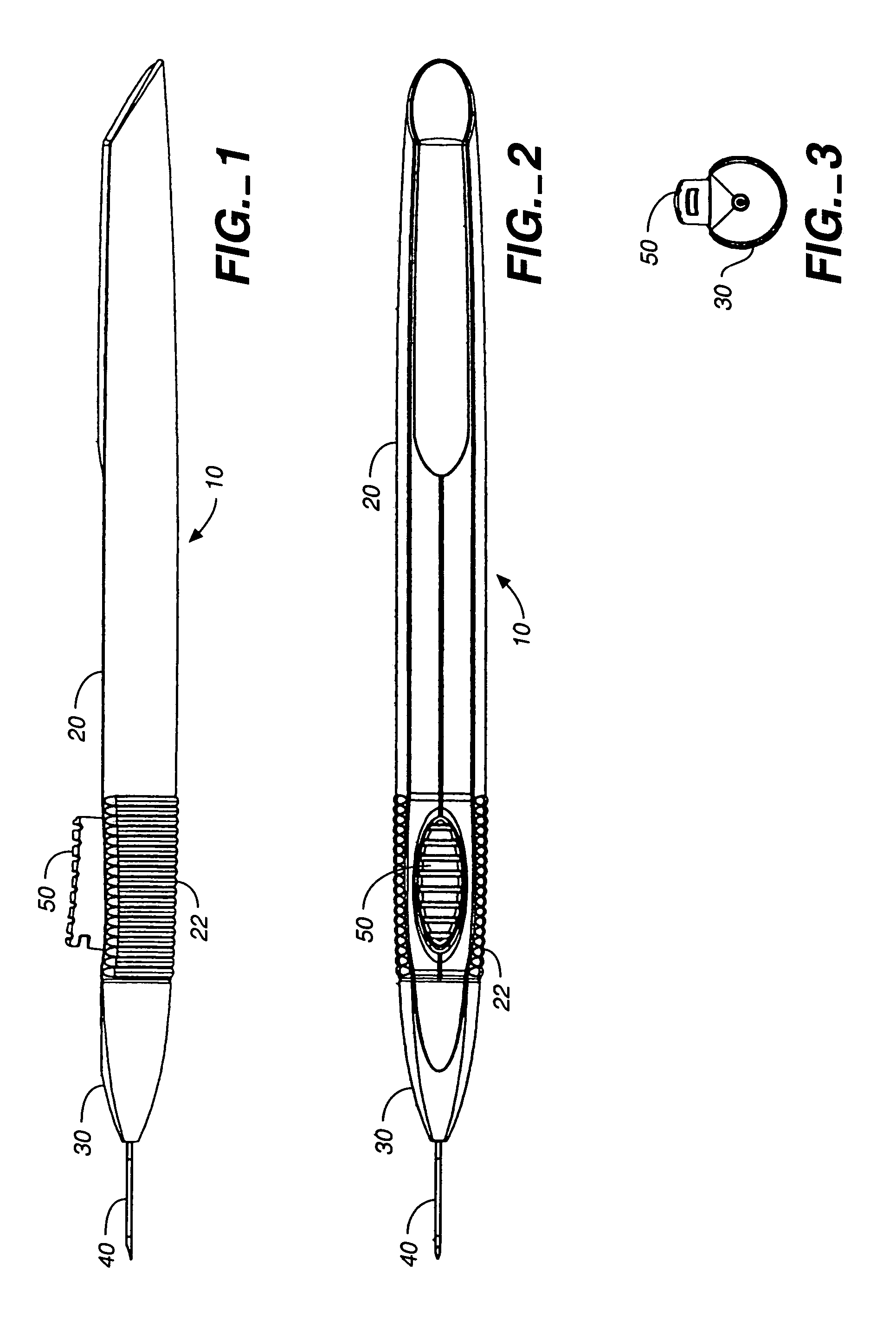
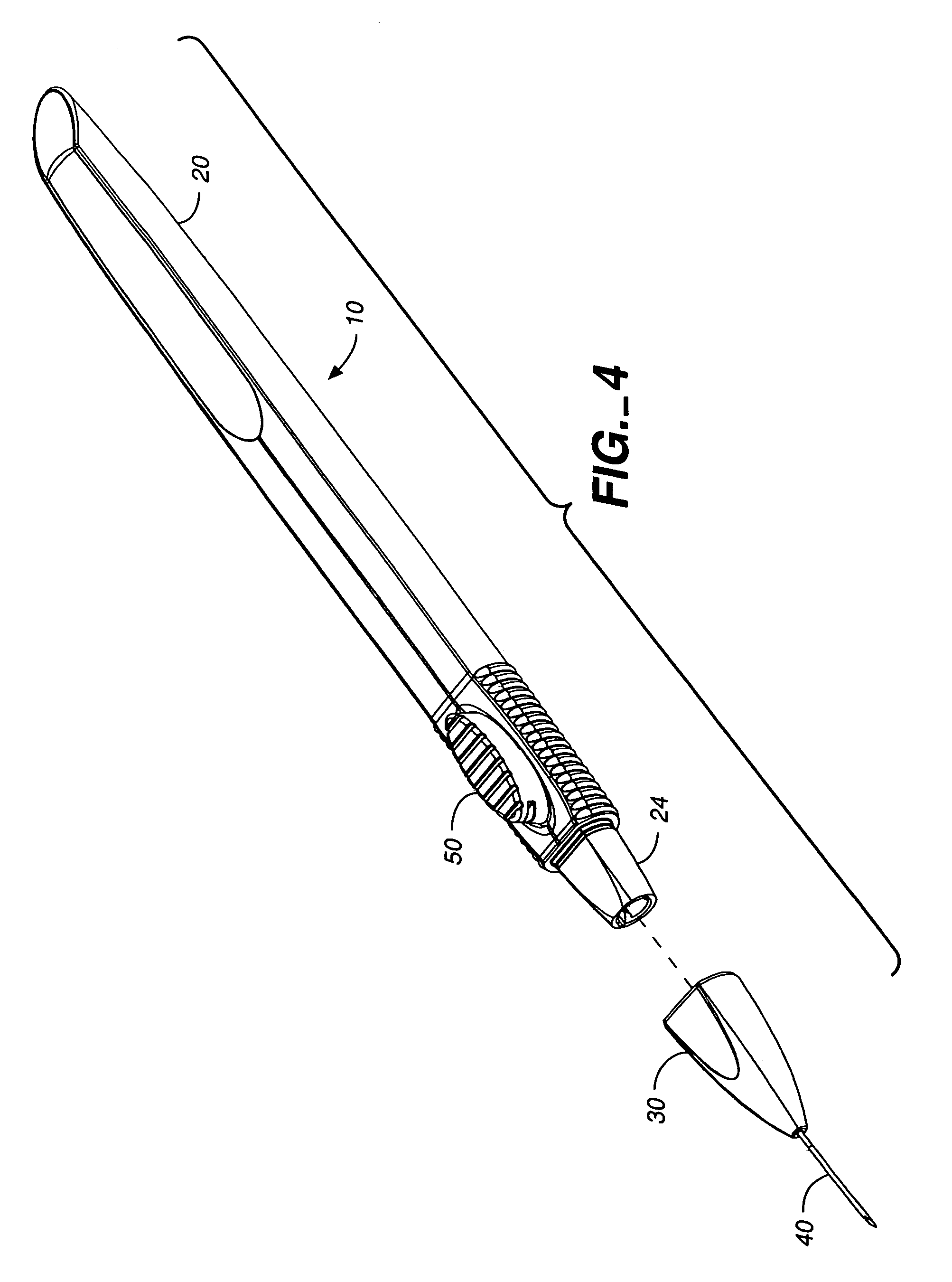
[0008]The present invention meets these and other needs and provides methods and apparatus for easily, safely, and more precisely delivering an implant into the eye.
[0014]The invention also provides methods of delivery of an implant into a location of the eye. In one aspect of the invention, a cannula is used having an outer diameter of 0.032 inches or less. In other aspects of the invention, a cannula is used having an outer diameter of 0.028 inches or less or 0.025 inches or less. In yet another aspect of the invention, in cases where the cannula has a non-circular cross-section, the cannula has a cross-sectional area of up to 0.0008 square inches or more, depending on the particular cross-sectional geometry. The use of cannulas having such cross-sectional dimensions allows for self-sealing methods of implant delivery.
[0015]Accordingly, in one embodiment, a method of delivering an ocular microimplant into a patient's eye is provided which involves providing a cannula having a distal sharpened tip, lumen extending through the cannula, a microimplant retained within the lumen, and a push rod received through a proximal end of the cannula. The cannula is then used to puncture through the outer layer of a patient's eye with the cannula and inserted to a desired location within the patient's eye to a desired location. Once the cannula is positioned, the push rod is moved from the proximal end of the cannula toward the distal end of the cannula, thereby ejecting the microimplant from the cannula. After ejection, the cannula and push rod are removed from the patient's eye, and the puncture created by the insertion of the cannula into the patient's eye is self-sealing upon the removal of the cannula. Particular orientations of the cannula during insertion can aid in self-sealing. The cannula tip can further be configured to have particular beveled designs which further aid in the self-sealing method.
[0016]While the delivery apparatus according to the invention facilitates the inventive method of delivering an ocular microimplant, it is not necessary to the practice of inventive method. For example, one skilled in the art can also use a needle and plunger assembly, where the needle has dimensions corresponding to the described cannula.
[0017]The methods and apparatus of the invention provide numerous advantages, not least of which is providing for an easier, convenient, and less traumatic means for delivering implants into the eye. In certain embodiments, the self-sealing means of implant delivery can be achieved, which in addition to being less invasive and traumatic, offers less costly treatment by obviating the need for performing the procedure in a surgical setting.
[0018]The methods and apparatus of the invention also provide for a more controlled means of delivering implants into the eye. In particular, embodiments of the inventive apparatus are designed to provide a smooth, controlled delivery of the implant. Additional embodiments provide for safety features which include, among other things, user feedback upon the ejection of an implant and locking mechanisms which prevent backflow of eye fluid after ejection and / or which also prevent reuse of the applicator. Another advantage of the inventive apparatus is ease and flexibility of manufacture and assembly of apparatuses for delivery of different implants.

Problems solved by technology

A primary difficulty in treating diseases of the eye is the inability to introduce drugs or therapeutic agents into the eye and maintain these drugs or agents at a therapeutically effective concentration in the eye for the necessary duration.
Systemic administration may not be an ideal solution because, often, unacceptably high levels of systemic dosing is needed to achieve effective intraocular concentrations, with the increased incidence of unacceptable side effects of the drugs.
Simple ocular instillation or application is not an acceptable alternative in many cases because the drug may be quickly washed out by tear-action or is otherwise depleted from within the eye into the general circulation.
Suprachoroidal injections of drug solutions have also been performed, but again the drug availability is short-lived.
Such methods make it difficult to maintain therapeutic levels of drug for adequate time periods.
Wherever the desired location of implantation, typical methods of implantation all require relatively invasive surgical procedures, pose a risk of excessive trauma to the eye, and require excessive handling of the implant.
The drawbacks of such techniques for implant delivery are many-fold.
Extensive handling of the implant is necessitated in these techniques, creating a risk that the implant will be damaged in the process.
Many such implants are polymer-based and are relatively fragile.
In addition, it becomes inherently difficult using these methods to achieve reproducible placement from patient to patient.

Method used


Image

  • Apparatus for delivery of ocular implants
  • Apparatus for delivery of ocular implants
  • Apparatus for delivery of ocular implants

Examples


example 1

Effects of Needle Size and Technique on Vitreous Leakage

[0076]Different gauge needles together with various insertion techniques were pursued to determine the maximum size needle gauge and optimum insertion technique for mimimum vitreous leakage and “self-sealing” wounds.

[0077]Eight rabbits were anaesthetized with a Ketamine / Xylazine cocktail. Drops of a 0.5% Opthaine solution were delivered to each eye of the rabbit as a local anaesthetic. 16 g, 20 g, 22 g, 23 g, 25 g needles (Beckton-Dickinson, Franklin Lakes, N.J.) were attached to syringes and inserted into the vitreous cavities of the rabbits' eyes, through the pars plana (2–3 mm from the limbus) according to varying techniques. For each needle size, the needles were inserted at either angles of 90° or 45° relative to the pars plana of the eye, or according to the following “tunnel” technique. In the “tunnel” technique, the needle is initially advanced into the first scleral layer of the eye tissue at a very shallow angle, almo...

example 2

Delivery of Microimplants

[0082]Cylindrical microimplants having dimensions of 0.015 inches diameter and 6 mm length were delivered into posterior segments of rabbits' eyes using a 23 gauge thin wall needle and according to insertion techniques described above in Example 1.

[0083]Four rabbits were anaesthetized as before with a Ketamine / Xylazine cocktail and with drops of a 0.5% Opthaine solution administered to each eye of the rabbit as a local anaesthetic. 23 g thin wall needles (BD, Franklin Lakes, N.J.) were attached to syringes and the needle cannulaes were loaded with the microimplants. The needles were inserted into the vitreous cavities of the rabbits' eyes, according to varying techniques detailed in Example 1 and as further described herein. Table 2A below details the needle gauge and insertion technique for each animal.

[0084]

TABLE 2ASTUDY DESIGNBevel position,AnimalEyeorientation of needle1ODUp, 90°OSDown, 90°2ODUp, 45°OSDown, 45°3ODUp, 45°OSDown, 45°4ODTunnel techniqueOSTu...


PUM


Abstract

An apparatus and methods for delivering ocular implants or microimplants. The apparatus is ergonomically designed for ease of use, and a simple manual depression of an actuator produces proportional movement of a linkage causing the implant or microimplant to be ejected through a cannula disposed at the desired location in the eye. Small gauge cannulas are provided for self-sealing methods of delivery.

Description

CROSS REFERENCE[0001]This application is a divisional of application Ser. No. 10 / 246,884, filed Sep. 18, 2002 now U.S. Pat. No. 6,899,717.TECHNICAL FIELD[0002]The present invention relates to methods and apparatus for delivering solid or semi-solid materials into the eye. Specifically, the methods and apparatus can be used to introduce implants containing therapeutic or active agents, including bioerodible implants, into various locations within the eye, including the vitreous of the eye.BACKGROUND ART[0003]A primary difficulty in treating diseases of the eye is the inability to introduce drugs or therapeutic agents into the eye and maintain these drugs or agents at a therapeutically effective concentration in the eye for the necessary duration. Systemic administration may not be an ideal solution because, often, unacceptably high levels of systemic dosing is needed to achieve effective intraocular concentrations, with the increased incidence of unacceptable side effects of the drug...

Claims


Application Information

Patent Timeline
Patent Type & Authority Patents(United States)
IPC IPC(8): A61F9/00
CPCA61F9/0017A61B17/3468
Inventor WEBER, DAVIDKANE, INGRIDREHAL, MIKELATHROP, III, ROBERT L.APTEKAREV, KENNY
Owner ALLERGAN INC
Learn More