Probe for use in determining an attribute of a coating on a substrate

a technology for coating attributes and probes, applied in the field of probes, can solve the problems of deleterious effects on the accuracy of copper thickness measurement, quick wear and tear of probe tip pins, etc., and achieve the effects of improving the visibility of a portion, easy removal, and improving the stability of the pin or pin

Inactive Publication Date: 2006-12-12
OXFORD INSTR MEASUREMENT SYST
View PDF7 Cites 80 Cited by
  • Summary
  • Abstract
  • Description
  • Claims
  • Application Information

AI Technical Summary

Benefits of technology

[0017]A second aspect of the invention relates to improved visibility of a portion of the probe that is located adjacent the coating. The probe has a housing having a receiving cavity with an access opening. The probe also has a light transmissive captivation structure that is mounted in the receiving cavity of the housing for communication through the receiving cavity access opening with the exterior of the probe. The probe further includes at least one electrically conductive pin that (1) has a portion captivated in a fixed orientation within the light transmissive captivation structure, (2) has a distal end projecting outwardly of the light transmissive captivation structure for engaging the coating, and (3) is connected with an electrical circuit adapted to provide electrical communication with the processing system. The probe also has a light emitting source in the housing for emitting light through the light transmissive captivation structure along the pin to illuminate the pin distal end. This permits the user to better observe the placement of the probe pin at a desired location on the coating.
[0018]According to a presently preferred embodiment of a probe incorporating this second aspect of the invention, the housing is a generally tubular, opaque structure, but the light transmissive captivation structure is molded from a transparent, thermoplastic material, such as polycarbonate, and is drilled to provide a hole or passage in which a portion of the pin is captivated and held in the desired fixed orientation. At least one contact is mounted in the tubular, opaque structure, and the contact is connected with the electrical circuit adapted to provide electrical communication with the processing system. The pin and the light transmissive captivation structure together define an integral unit in the form of a probe tip that has (1) an inner portion that is received in the housing so as to effect engagement between the pin and the contact, and (2) an extending portion that projects from the housing at the receiving cavity access opening. The tip may or may not be designed to be readily removable from the housing by the user.
[0019]A third aspect of the invention relates to a probe which uses a pin or pins to engage a coating and which provides better stabilization of the pin or pins. The probe provides electrical communication between the coating and a processing system wherein the processing system determines an attribute of the coating, such as the thickness of the coating, by detection of phenomena resulting from the application of electrical energy to the pin in contact with the coating.

Problems solved by technology

The inventors have determined that precision and accuracy of the copper thickness measurement can be deleteriously affected by lateral displacement of the pin point 170 which could occur in conventional prior art probe systems prior to, and during, engagement of the pin point with the copper coating.
In some measurement applications, the probe tip pins can be quickly worn down because the printed circuit boards are slid out of the measurement station before the probe tip has been lifted completely off of the copper coating.

Method used


Image

  • Probe for use in determining an attribute of a coating on a substrate
  • Probe for use in determining an attribute of a coating on a substrate
  • Probe for use in determining an attribute of a coating on a substrate

Examples


Embodiment Construction

[0056]While this invention is susceptible of embodiment in many different forms, this specification and the accompanying drawings disclose only some specific forms as examples of the invention. The invention is not intended to be limited to the embodiments so described, however. The scope of the invention is pointed out in the appended claims.

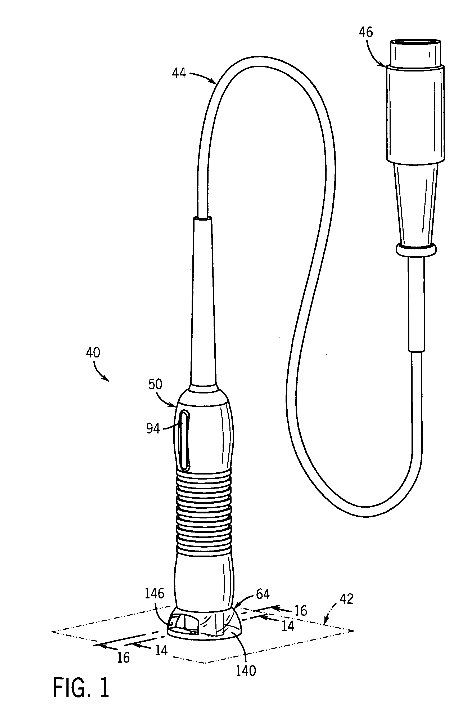
[0057]For ease of description, the probe of this invention is described in the normal (upright) operating position, and terms such as upper, lower, horizontal, etc., are used with reference to this position. It will be understood, however, that the probe of this invention may be manufactured, stored, transported, used, and sold in an orientation other than the position described.

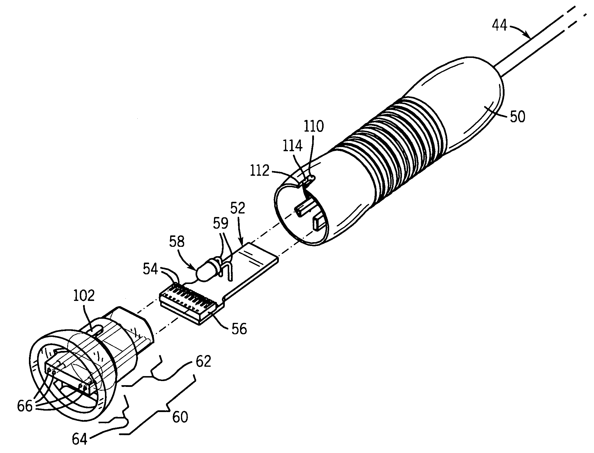
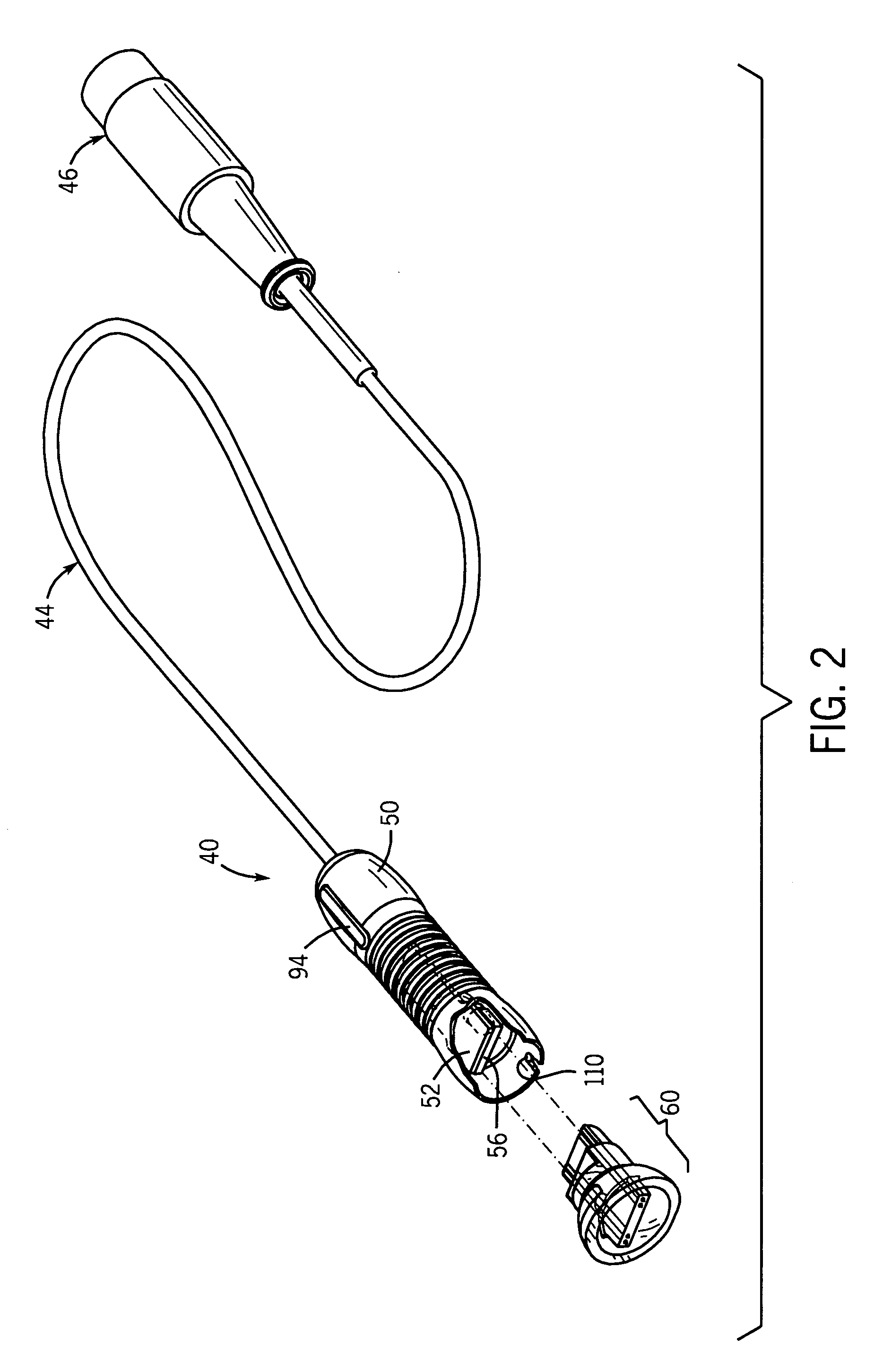
[0058]Figures illustrating the probe show some conventional electrical, mechanical, and structural elements that are known and that will be recognized by one skilled in the art. The detailed descriptions of such elements are not necessary to an understanding of the inve...


PUM


Abstract

A probe provides electrical communication between a coating and a processing system. One optional feature includes an outwardly projecting, electrically conductive engaging member that is held in a captivation structure releasably retained in a housing and engages a contact that is inside the probe and connected with the processing system. Another optional feature of the probe provides the electrically conductive engaging member in the form of a pin or pins captivated in a light-transmissive structure adjacent a light-emitting source. Another optional feature of the probe includes a restraining structure that defines a frustoconical seat for engaging a conical distal end of an electrically conductive pin that is adapted to contact the coating.

Description

CROSS REFERENCE TO RELATED APPLICATION(S)[0001]None.STATEMENT REGARDING FEDERALLY SPONSORED RESEARCH OR DEVELOPMENT[0002]None.REFERENCE TO A MICROFICHE APPENDIX[0003]None.TECHNICAL FIELD[0004]This invention relates to a probe for providing electrical communication between a material (e.g., a coating defined by a film or layer on a substrate) and a processing system (e.g., analyzing system) that determines an attribute of the material (e.g., the thickness of a coating) by analysis of detected or sensed phenomena in the material (e.g., an electrical characteristic temporarily established in the material as a result of the application of electrical energy to the probe near, or in contact with, the material).BACKGROUND OF THE INVENTION AND TECHNICAL PROBLEMS POSED BY THE PRIOR ART[0005]Some attributes (i.e., characteristics or features) of a material can be determined (e.g., measured) with an appropriate instrument. For example, various models of instruments for non-destructively measur...

Claims


Application Information

Patent Timeline
Patent Type & Authority Patents(United States)
IPC IPC(8): G01R31/02
CPCG01R1/06788
Inventor PREY, JR., JOHN E.TOM, JOSEPH
Owner OXFORD INSTR MEASUREMENT SYST
Why Eureka
Try Eureka