Contact assembly

a contact and circuit breaker technology, applied in the direction of contact mechanisms, circuit breakers, switch contacts, etc., can solve the problem of not being as strong as other materials, and achieve the effect of improving short-circuit interruption performan

Inactive Publication Date: 2006-12-12
EATON CORP
View PDF7 Cites 18 Cited by
  • Summary
  • Abstract
  • Description
  • Claims
  • Application Information

AI Technical Summary

Benefits of technology

[0008]These needs and others are met by the present invention, which greatly improves the short-circuit interruption performance of circuit break

Problems solved by technology

Normally, a movable contact arm is made of solid copper or alloys of copper (e.g., silver bearing copper; a copper alloy with a relatively s

Method used


Image

  • Contact assembly
  • Contact assembly
  • Contact assembly

Examples


example 1

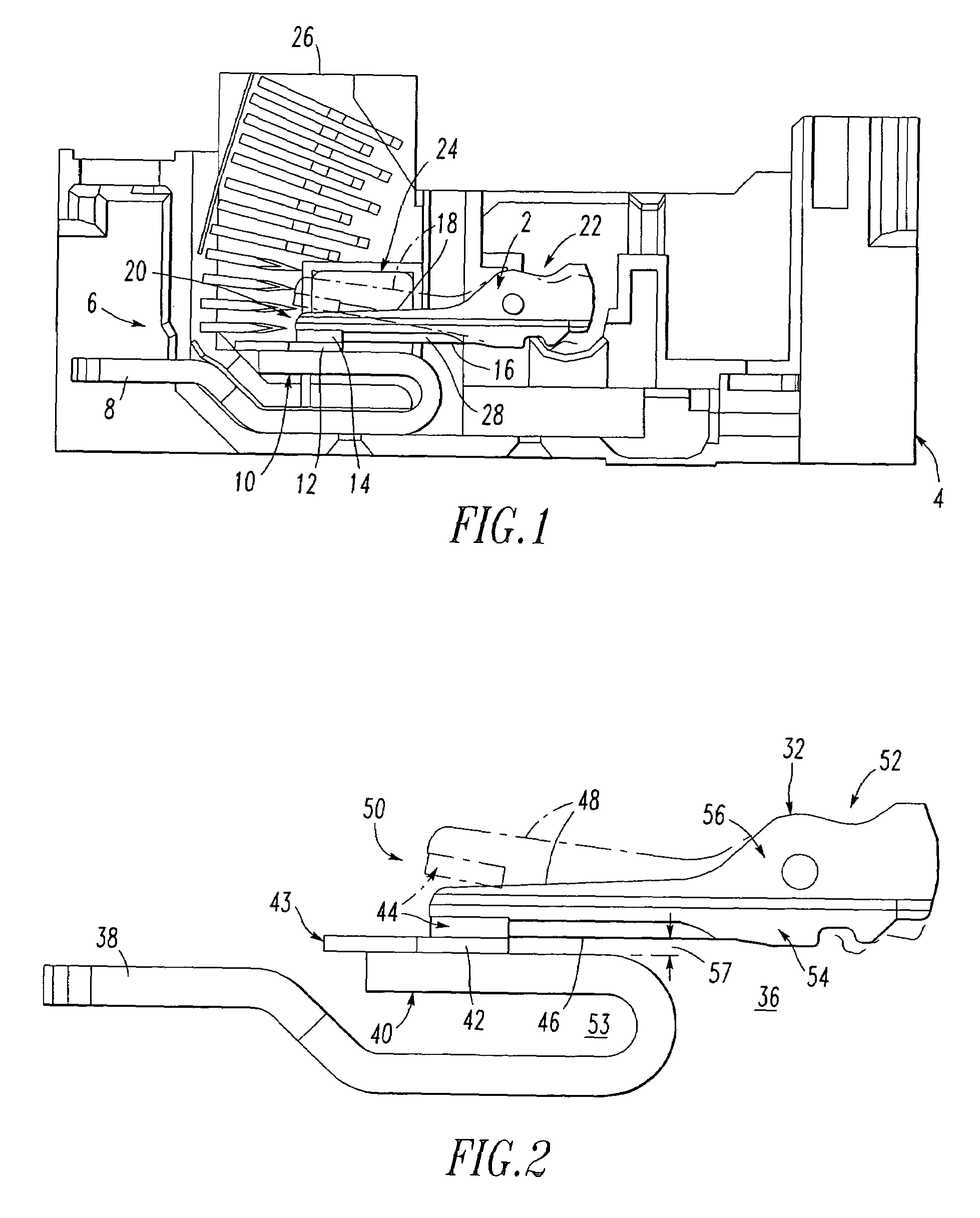
[0038]FIG. 1 shows a movable contact arm 2 as employed in a molded case circuit breaker (MCCB) 4. A contact assembly 6 for the MCCB 4 includes a line conductor 8 having a folded back fixed contact end 10, a fixed contact 12 mounted on the line conductor fixed contact end 10, a movable contact 14, and the movable contact arm 2. The movable contact arm 2 has an inner edge 16, an outer edge 18, a first end 20 and a second end 22. The movable contact 14 is mounted on the first end 20. The movable contact arm 2 is pivotable about the second end 22 between a closed position (as shown in FIG. 1) in which the inner edge 16 extends adjacent the folded back fixed contact end 10 with the movable contact 14 in electrical and mechanical contact with the fixed contact 12 to form a reverse current loop and an open position (shown in phantom line drawing in FIG. 1) in which the movable contact 14 is pivoted away from the fixed contact 12.

[0039]In accordance with an important aspect of the invention...

example 2

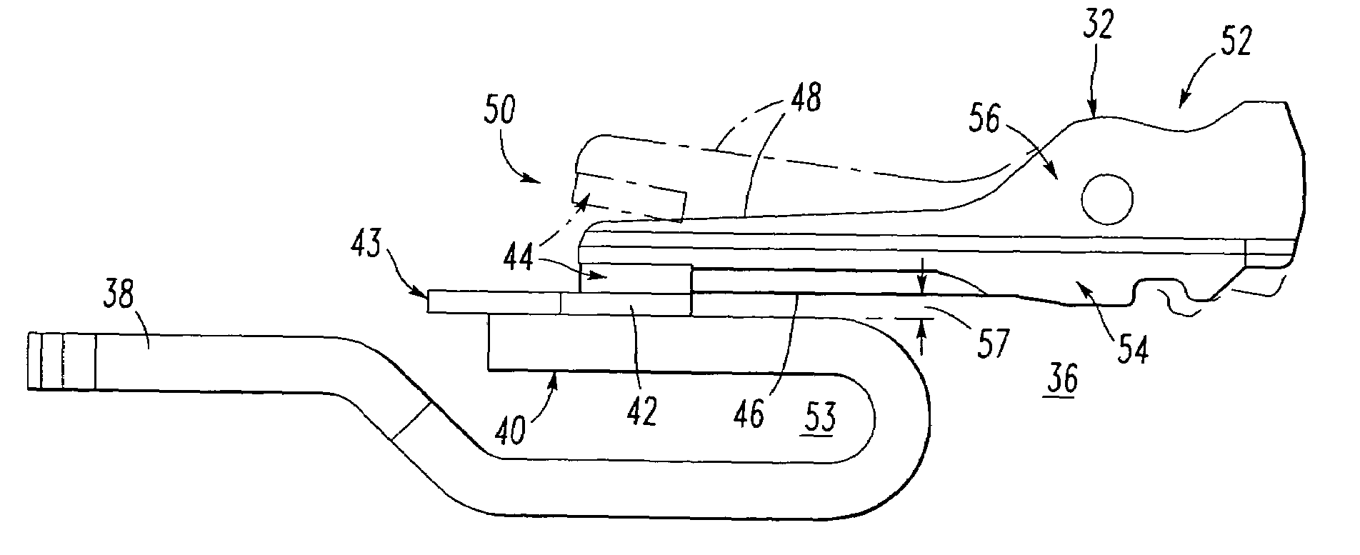
[0042]FIG. 2 shows a hybrid movable contact arm 32 of a contact assembly 36. The contact assembly 36 includes a line conductor 38 having a folded back fixed contact end 40, a fixed contact 42 mounted on the line conductor fixed contact end 40, an arc runner 43, and a movable contact 44. The movable contact arm 32 has an inner edge 46, an outer edge 48, a first end 50 and a second end 52. The movable contact 44 is mounted on the first end 50 and is pivotable about the second end 52 between a closed position (as shown in FIG. 2) in which the inner edge 46 extends adjacent the folded back fixed contact end 40 with the movable contact 44 in electrical and mechanical contact with the fixed contact 42 to form a reverse current loop 53 and an open position (shown in phantom line drawing in FIG. 2) in which the movable contact 44 is pivoted away from the fixed contact 42. The movable contact arm 32 includes a first inner longitudinal member 54 extending along the inner edge 46 and a second ...

example 3

[0046]Although aluminum and an aluminum alloy are disclosed, any suitable relatively high tensile and shear strength, low specific density (e.g., light weight) and relatively lower electrical conductivity material may be employed. As a non-limiting example, a suitable material made from molding plastic resin with carbon fibers may be employed.


PUM


Abstract

A circuit breaker contact assembly includes a line conductor having a folded back fixed contact end, a fixed contact mounted on the contact end, and a movable contact arm having an inner edge and first and second ends. A movable contact is mounted on the first end. The movable contact arm is pivotable about the second end between a closed position in which the inner edge extends adjacent the contact end with the movable contact in contact with the fixed contact to form a reverse current loop, and an open position in which the movable contact is pivoted away from the fixed contact. The contact arm includes a first inner longitudinal member extending along the inner edge and a second outer longitudinal member. The first inner longitudinal member has a higher electrical conductivity than the second outer longitudinal member, which has a higher shear strength and a lower specific density.

Description

BACKGROUND OF THE INVENTION[0001]1. Field of the Invention[0002]The present invention relates generally to circuit interrupters and, more particularly, to contact assemblies for circuit breakers.[0003]2. Background Information[0004]Circuit interrupters, such as circuit breakers, are employed in diverse capacities in power distribution systems. A circuit breaker may include, for example, a line conductor, a load conductor, a fixed contact and a movable contact, with the movable contact being movable into and out of electrically conductive engagement with the fixed contact. This switches the circuit breaker between an on or closed position and an off or open position, or between the on or closed position and a tripped or tripped off position. The fixed contact is electrically conductively engaged with one of the line and load conductors, and the movable contact is electrically conductively engaged with the other of the line and load conductors. The circuit breaker may also include an ...

Claims


Application Information

Patent Timeline
IPC IPC(8): H01H83/00
CPCH01H1/22H01H11/06H01H73/04
Inventor SHEA, JOHN J.MILLER, JEFFREY A.
Owner EATON CORP
Why Eureka
Try Eureka