Microwave tunable inductor and associated methods

a technology of inductor and microwave region, applied in the field of wireless communication, can solve the problems of tunable coil slug, low efficiency and q value, and inability to use above vhf,

Active Publication Date: 2006-12-12
HARRIS CORP
View PDF7 Cites 57 Cited by
  • Summary
  • Abstract
  • Description
  • Claims
  • Application Information

AI Technical Summary

Problems solved by technology

Inductors for the microwave region can become too small to fabricate and suffer low efficiency and Q values.
For instance, the ferrite core, or tunable coil slug, is unusable above VHF due to eddy current losses in the ferrite.
Even printed spiral inductors have limited usefulness at microwave frequencies, as magnetic field circulation through silicon substrates results in eddy-current loss, and a higher than normal parasitic capacitance.

Method used


Image

  • Microwave tunable inductor and associated methods
  • Microwave tunable inductor and associated methods
  • Microwave tunable inductor and associated methods

Examples


Embodiment Construction

[0015]The present invention will now be described more fully hereinafter with reference to the accompanying drawings, in which preferred embodiments of the invention are shown. This invention may, however, be embodied in many different forms and should not be construed as limited to the embodiments set forth herein. Rather, these embodiments are provided so that this disclosure will be thorough and complete, and will fully convey the scope of the invention to those skilled in the art. Like numbers refer to like elements throughout.

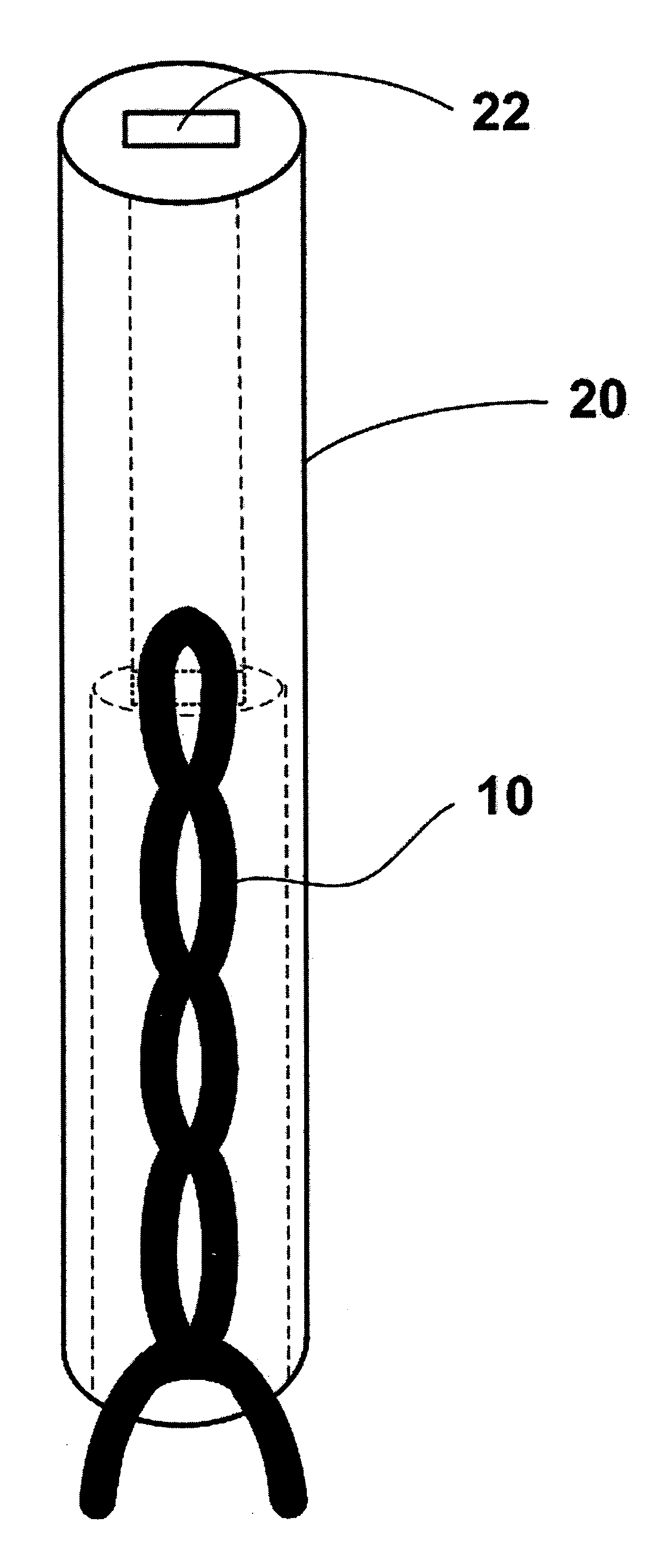
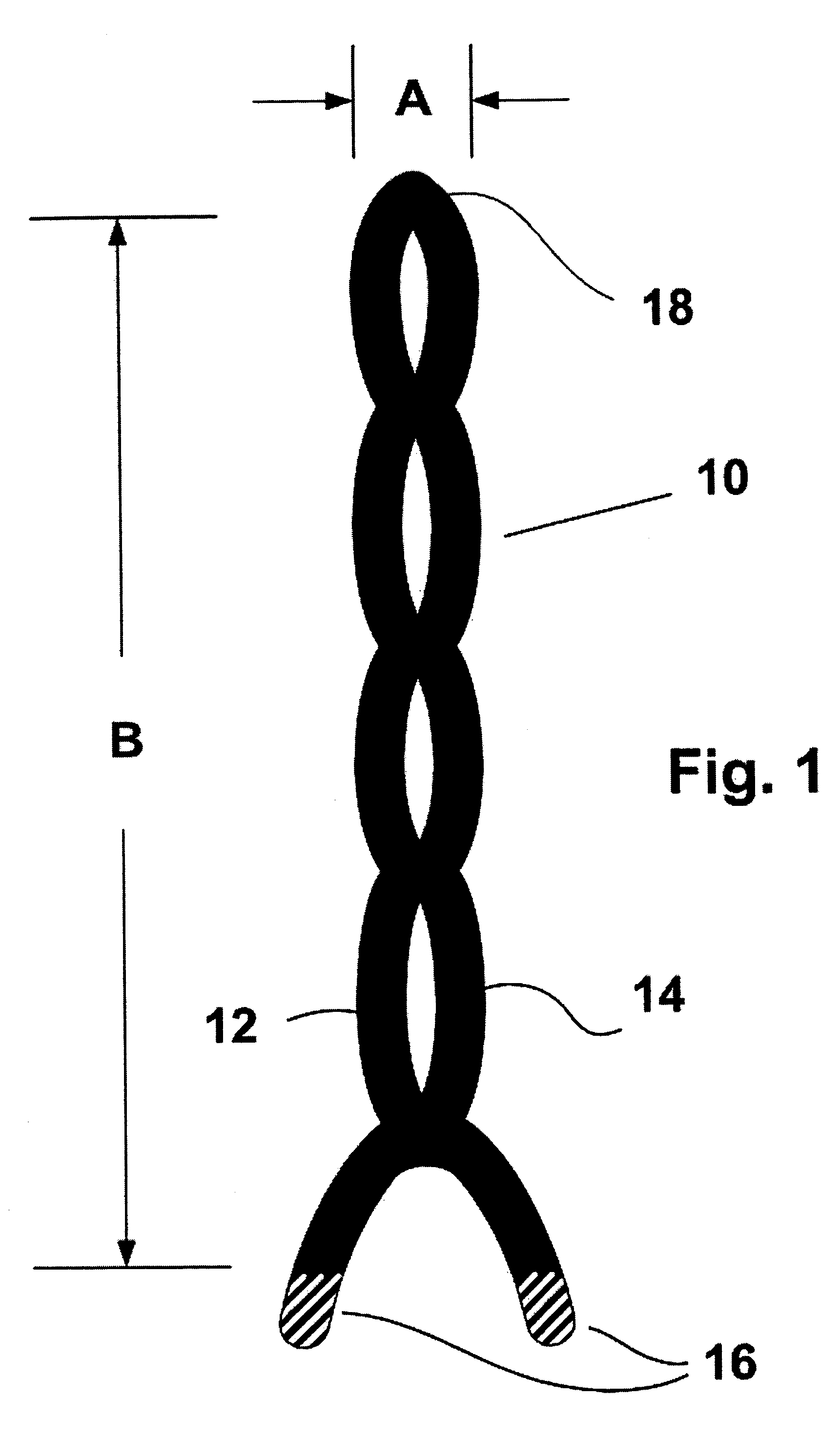
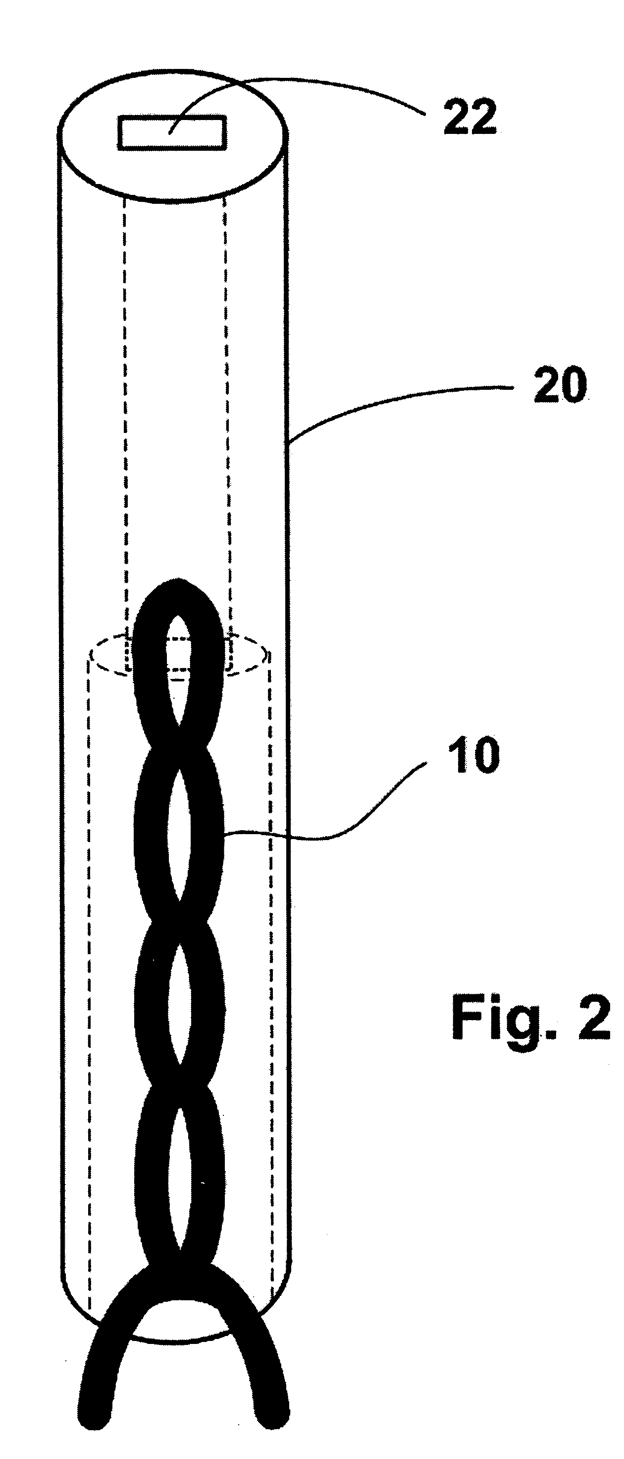
[0016]Referring initially to FIG. 1, an inductor 10, such as a microwave tunable inductor or bifilar helix inductor, in accordance with the present invention will now be described. The inductor 10 includes first 12 and second 14 wires twisted together to define a double helix having a first end and second end with a plurality of twists therebetween. First and second terminals 16 are at the first end of the double helix, and a connection 18 at the second en...


PUM

PropertyMeasurementUnit
inductanceaaaaaaaaaa
lengthaaaaaaaaaa
lengthaaaaaaaaaa

Abstract

The inductor, preferably a microwave tunable inductor, includes first and second wires twisted together to define a double helix having a first end and second end with a plurality of twists therebetween. First and second terminals are at the first end of the double helix, and a connection at the second end of the double helix electrically connects the first and second wires in series. The inductance is tuned by adjusting a number of twists in the double helix, and the inductance includes a linear tuning range based upon between about 3 to 10 twist for a tuning range of about 7–12 Nanohenries. The inductor can also resonate and filter, and the double helix affords numerous advantages over conventional single helix inductors.

Description

FIELD OF THE INVENTION[0001]The present invention relates to the field of wireless communications, and more particularly, the invention relates to a microwave inductor with linear tuning and related methods.BACKGROUND OF THE INVENTION[0002]Inductors are a fundamental electromagnetic component necessary to a wide variety of devices, such as actuators, relays, motors, DC-to-DC converters and radio frequency (RF) circuits. Inductors having large inductances typically include wires wrapped around a bulk dielectric or ferromagnetic core, and are used in power converters and relays. Radio frequency inductors having small inductances typically are helical coils having an air or ferrite core, and are used in RF circuits and communications equipment.[0003]Inductors for the microwave region can become too small to fabricate and suffer low efficiency and Q values. Conventional RF inductor techniques must often be abandoned. For instance, the ferrite core, or tunable coil slug, is unusable abov...

Claims


Application Information

Patent Timeline
Patent Type & Authority Patents(United States)
IPC IPC(8): H01F27/28
CPCH01F21/005H01F21/04
Inventor PARSCHE, FRANCIS EUGENERUIZ, ENRIQUE
Owner HARRIS CORP
Why Eureka
Try Eureka