Over-power protection apparatus with programmable over-current threshold

Active Publication Date: 2006-12-12
SEMICON COMPONENTS IND LLC
View PDF10 Cites 120 Cited by
  • Summary
  • Abstract
  • Description
  • Claims
  • Application Information

AI Technical Summary

Benefits of technology

[0007]In view of the foregoing shortcomings, the over-power protection apparatus used in a power supply for programming an over-current threshold provides a peak power adjusted according to a load requirement. The circuit according to a first preferred embodiment of the present invention comprises an oscillator for outputting a pulse signal. A control unit generates a clear signal once the current sense signal exceeds a maximum power threshold. A driving unit outputs a driving signal for controlling the driving unit to periodically disable the driving signal in response to the clear signal. A threshold unit generates a current limit signal in response to the driving signal is in high-level. An over-power comparative unit outputs a protection signal once the current sense signal is higher than the current limit signal. An accumulating trigger

Problems solved by technology

A limited power output is thus required for the power converter during the conditions for overloading, short-circuit and feedback open-loop.
The peak power is always equal to several times of the maximum output power, such that the power

Method used


Image

  • Over-power protection apparatus with programmable over-current threshold
  • Over-power protection apparatus with programmable over-current threshold
  • Over-power protection apparatus with programmable over-current threshold

Examples


Embodiment Construction

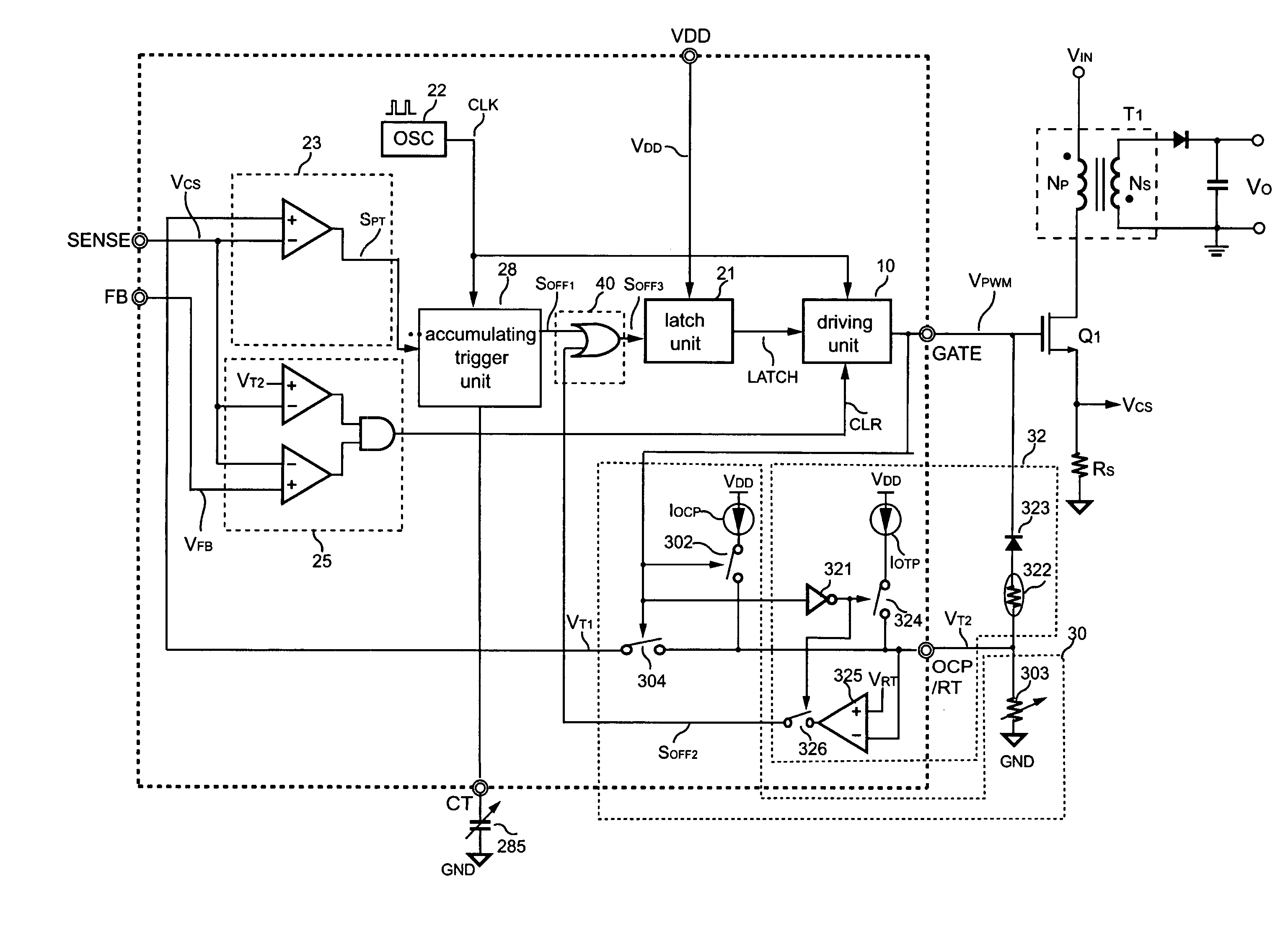
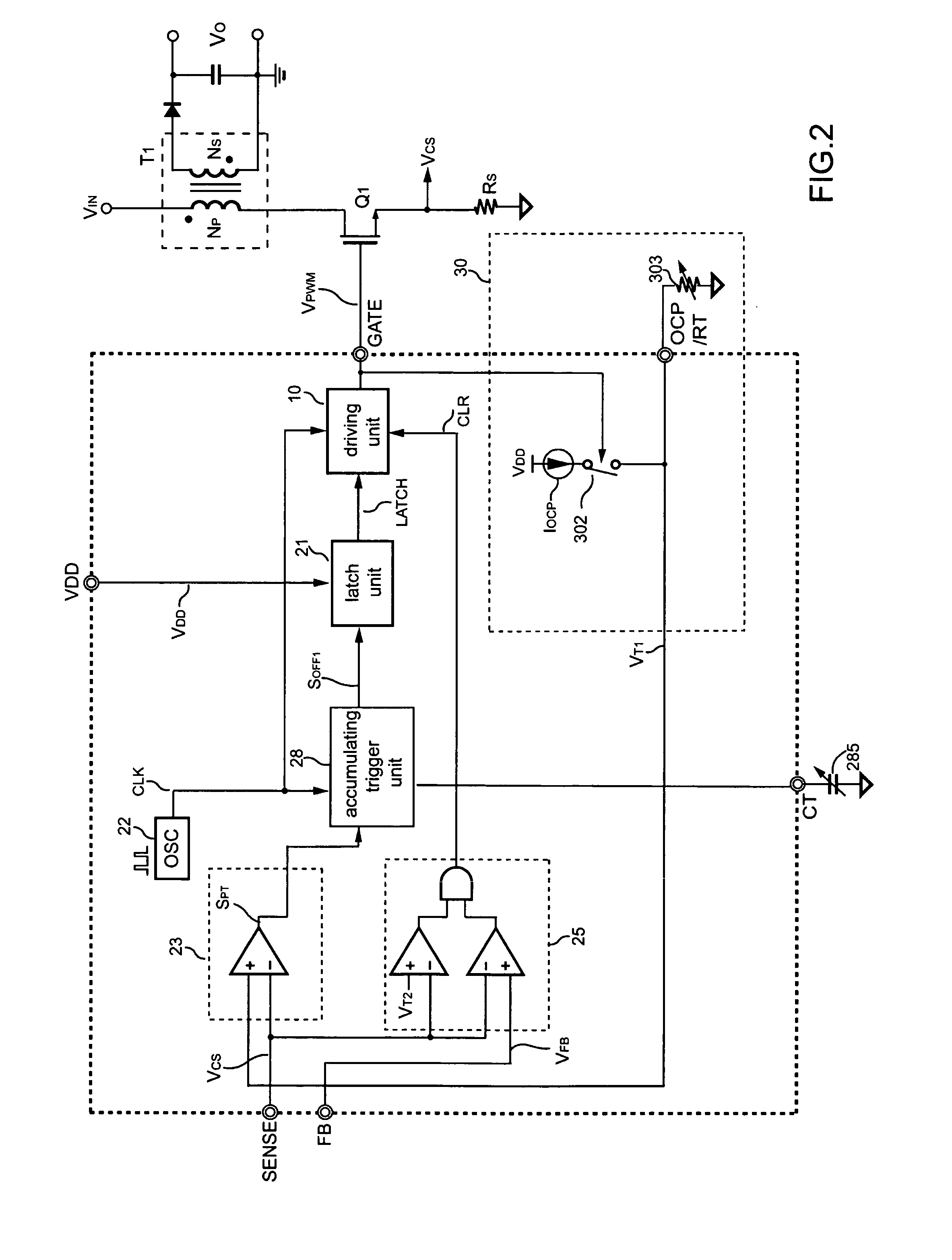
[0015]FIG. 2 shows a first preferred embodiment of a schematic diagram of a power converter according to the present invention. The first preferred embodiment comprises an oscillator 22 for outputting a pulse signal CLK. A control unit 25 receives a current sense signal VCS, a voltage feedback signal VFB, and a maximum power signal VT2 for generating a clear signal CLR in a low-level once the current sense signal VCS is higher than the maximum power signal VT2 or the voltage feedback signal VFB. A driving unit 10 is connected to an oscillator 22 and a control unit 25 for receiving the pulse signal CLK to output a driving signal VPWM, and adjusting a pulse width of the driving signal VPWM once the clear signal CLR in low-level is produced.

[0016]A threshold unit 30 is connected to the driving unit 10 for outputting a current limit signal VT1 in response to the driving signal VPWM is in high-level. The threshold unit 30 comprises a programming resistor 303 connected to a first controll...


PUM


Abstract

An over-power protection apparatus with programmable over-current threshold for a power converter is provided. The over-power protection apparatus further provides an over-temperature threshold for protection purposes. The over-power protection apparatus is able to achieve over-power and over-temperature protection in response to the level of the driving signal of the power converter. In addition, the programmable over-current threshold of the present invention can be adjusted in response to various load conditions.

Description

BACKGROUND OF THE INVENTION[0001]1. Field of the Invention[0002]The present invention relates to an over-power protection apparatus, and more particular to an over-power protection apparatus used in a power supply for programming an over-current threshold.[0003]2. Description of Related Art[0004]Various power converters have been widely used to provide a regulated output voltage and current. For the sake of safety reasons, an over-power protection means must be provided to protect both the power converter itself and the power system. A limited power output is thus required for the power converter during the conditions for overloading, short-circuit and feedback open-loop.[0005]Referring to FIG. 1 for the circuit diagram of a prior art power converter, the power converter comprises a transformer T1, a control unit 14, a driving unit 10, an oscillator 12, a current sense resistor RS, and a power switch Q1. The output terminal of the power converter can obtain a voltage feedback signal...

Claims


Application Information

Patent Timeline
IPC IPC(8): H02H7/122
CPCH02M1/32H02M3/33507H02H3/006
Inventor CHEN, TSO-MIN
Owner SEMICON COMPONENTS IND LLC
Why Eureka
Try Eureka