Auto-focusing lens with progressive variable focal element

a technology of progressive variable focal element and auto-focusing lens, which is applied in the field of auto-focusing lenses, can solve the problems of difficult to move the lens assembly fast enough, the lens assembly becomes more complicated with more elements, etc., and achieves the effects of less inertia, less space required, and less complexity

Active Publication Date: 2006-12-12
INTELLECTUAL VENTURES II
View PDF5 Cites 4 Cited by
  • Summary
  • Abstract
  • Description
  • Claims
  • Application Information

AI Technical Summary

Benefits of technology

[0004]An improved method and module for auto focusing utilizes a variable thickness focus element. A different thickness, and thus a different focus, is optically coupled to an image sensor by rotating the focus element. Movement along the optic axis is not required. This minimizes the amount of space required to provide the auto focusing function, allowing a mobile device utilizing the module to be smaller while still providing the auto focusing feature. In addition, the mechanism for rotating the focus element is smaller and/or less compl...

Problems solved by technology

When the mobile camera reach multi-million pixels resolutions, the lens assembly becomes more com...

Method used


Image

  • Auto-focusing lens with progressive variable focal element
  • Auto-focusing lens with progressive variable focal element
  • Auto-focusing lens with progressive variable focal element

Examples


first embodiment

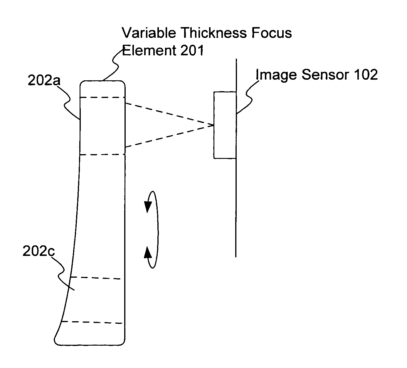
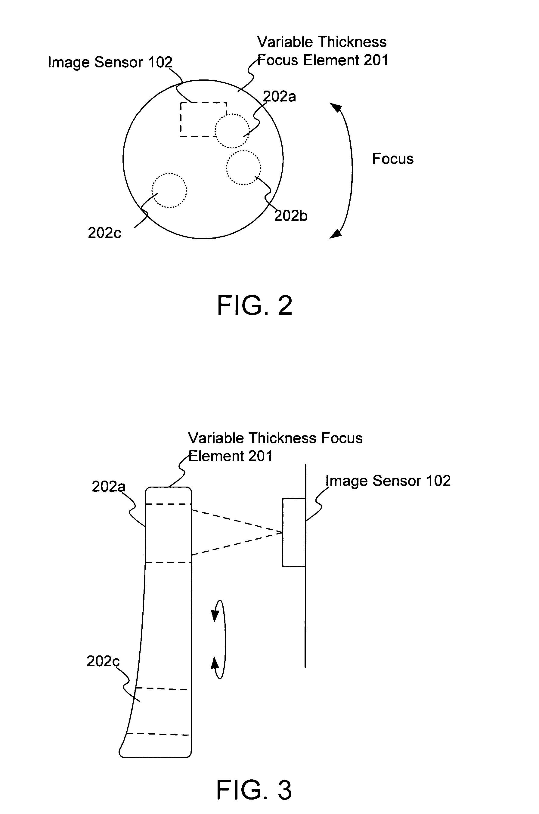
[0010]FIGS. 2 and 3 illustrate an image module for auto focusing in accordance with the present invention. FIG. 2 illustrates a front view, while FIG. 3 illustrates a side view. The image module includes a variable thickness focus element 201 for focusing an image onto the image sensor 102, such as portion 202a as illustrated in FIG. 3. The focus element 201 can be moved to optically couple different portions 202a–202c with the image sensor 102. Each portion 202a–202c has a different thickness, providing a different focus onto the image sensor 102. In this embodiment, the focus element 201 is rotated, such as on a spindle (not shown). Other manners of moving the focus element 201 are possible.

[0011]Unlike conventional focusing systems, the focus element 201 need not move along the optic axis in order to focus an image onto the image sensor 102. The amount of space required for the movement of the focus element 201 is significantly less. When used in a mobile device, such as a mobile...

second embodiment

[0012]FIG. 4 illustrates the image module for auto focusing in accordance with the present invention. In this embodiment, a compensation element 203 is added along the optic path between the focus element 201 and the image sensor 102. The compensation element 203 corrects for any imperfections in the focus onto the image sensor 102. For example, if the focus element 201 has a progressively variable thickness, the compensation element 203 can correct for gradients that occur between the target lengths. It can also serve as a protective window for the image sensor 102. In this embodiment, the compensation element 203 is fixed, but it can be moveable as well. It is also easier to produce than conventional lens assemblies.

third embodiment

[0013]FIG. 5 illustrates the image module for auto focusing in accordance with the present invention. In this embodiment, the focus element 201 includes a dark portion 204. When the focus element 201 is moved so that the dark portion 204 is in front of the image sensor 102, the dark portion 204 functions as a closed shutter, where no light reaches the image sensor 102. This eliminates the need for a separate shutter mechanism, further allowing the mobile device to be smaller.

[0014]An improved method and module for auto focusing has been disclosed. The method and module utilizes a variable thickness focus element. A different thickness, and thus a different focus, is optically coupled to an image sensor by rotating the focus element. Movement along the optic axis is not required. This minimizes the amount of space require to provide the auto focusing function, allowing a mobile device utilizing the module to be smaller. The dark portion of the focusing element also can provide a zero...


PUM


Abstract

An improved method and module for auto focusing utilizes a variable thickness focus element. A different thickness, and thus a different focus, is optically coupled to an image sensor by rotating the focus element. Movement along the optic axis is not required. This minimizes the amount of space required to provide the auto focusing function, allowing a mobile device utilizing the module to be smaller while still providing the auto focusing feature. In addition, the mechanism for rotating the focus element is smaller and/or less complex than a mechanism for moving a lens assembly along the optic axis, further allowing the device to be smaller. The focus element has less inertia than conventional lens assemblies and so required less power to move and allows for fast focusing.

Description

FIELD OF THE INVENTION[0001]The present invention relates to auto focusing lenses, and more particularly to auto focusing lenses in mobile devices.BACKGROUND OF THE INVENTION[0002]FIG. 1 illustrates a conventional auto focusing system. The system includes a lens assembly 101 for focusing an image onto an image sensor 102. To facilitate the focusing of the image, the lens assembly 101 moves along the optic axis, i.e., along the focus arrow illustrated in FIG. 1. Thus, a certain amount of space is required to allow the required range of movement by the lens assembly 101. When used in a mobile device, such as a mobile phone camera, this required space limits how small the device can be. The mechanical mechanism required to move the lens assembly 101 also requires space and power.[0003]Accordingly, there exists a need for an improved method and module for auto focusing. The improved method and module should minimize the amount of space required to facilitate the auto focusing function. ...

Claims


Application Information

Patent Timeline
IPC IPC(8): G03B17/00G03B13/00G03B7/099G03B9/10H04N5/238
CPCG03B13/36H04N5/23212H04N23/67
Inventor FENG, CHEN
Owner INTELLECTUAL VENTURES II
Why Eureka
Try Eureka