Providing multiple perspectives for a venue activity through an electronic hand held device

Inactive Publication Date: 2006-12-12
FRONT ROW TECH
View PDF58 Cites 336 Cited by
  • Summary
  • Abstract
  • Description
  • Claims
  • Application Information

AI Technical Summary

Benefits of technology

[0035]A system for receiving at least one perspective of a venue-based activity at a hand held device is additionally disclosed herein. Such a system includes at least one receiver for receiving at a hand held device at least one perspective of a venue-based activity transmitted from at least one venue-based data source. Such a system also incorporates a processor for processing one or more perspectives of the venue-based activity for display on a display screen associated with the hand held device. Additionally, such a system can be configured with a display screen for displaying at least one perspective view, thereby enabling a user of the hand held device to view perspectives of venue-based activity through the hand held device. The display screen may be integrated with the hand held device.
[0036]Another system disclos

Problems solved by technology

Despite the availability of such large screen television monitors, venue event audience members still lack enhanced viewing options or perspectives within the stadium itself.
Such binoculars can permit the typical audience member to obtain a somewhat better, but limited, view of the event, such as a football or hockey game, but even these views are often obstructed by other audience members and are tied to only one perspective.
The movement of the game ball in a football game, for example, along with the players on the field is dynamic and unpredictable, and may not always be caught by the active camera having the best perspective.
Thus, during a game, the large television screens typically provide only one view, which can be obstructed further by other players or officials, often destroying a critical angular view.
The audience members, therefore, essentially view the large screen at the behest of the camera operator and cannot select their own views or camera

Method used


Image

  • Providing multiple perspectives for a venue activity through an electronic hand held device
  • Providing multiple perspectives for a venue activity through an electronic hand held device
  • Providing multiple perspectives for a venue activity through an electronic hand held device

Examples


Embodiment Construction

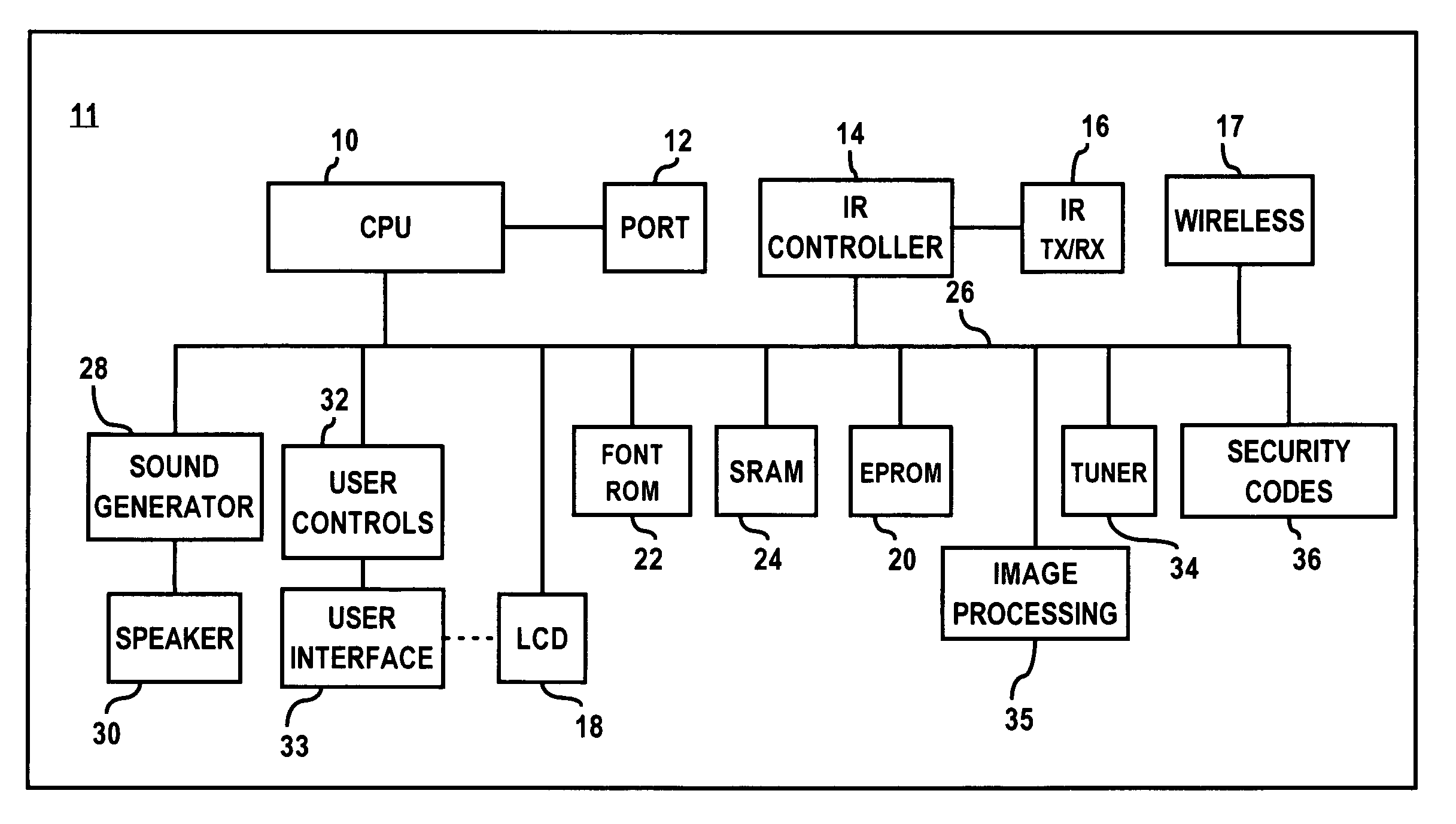
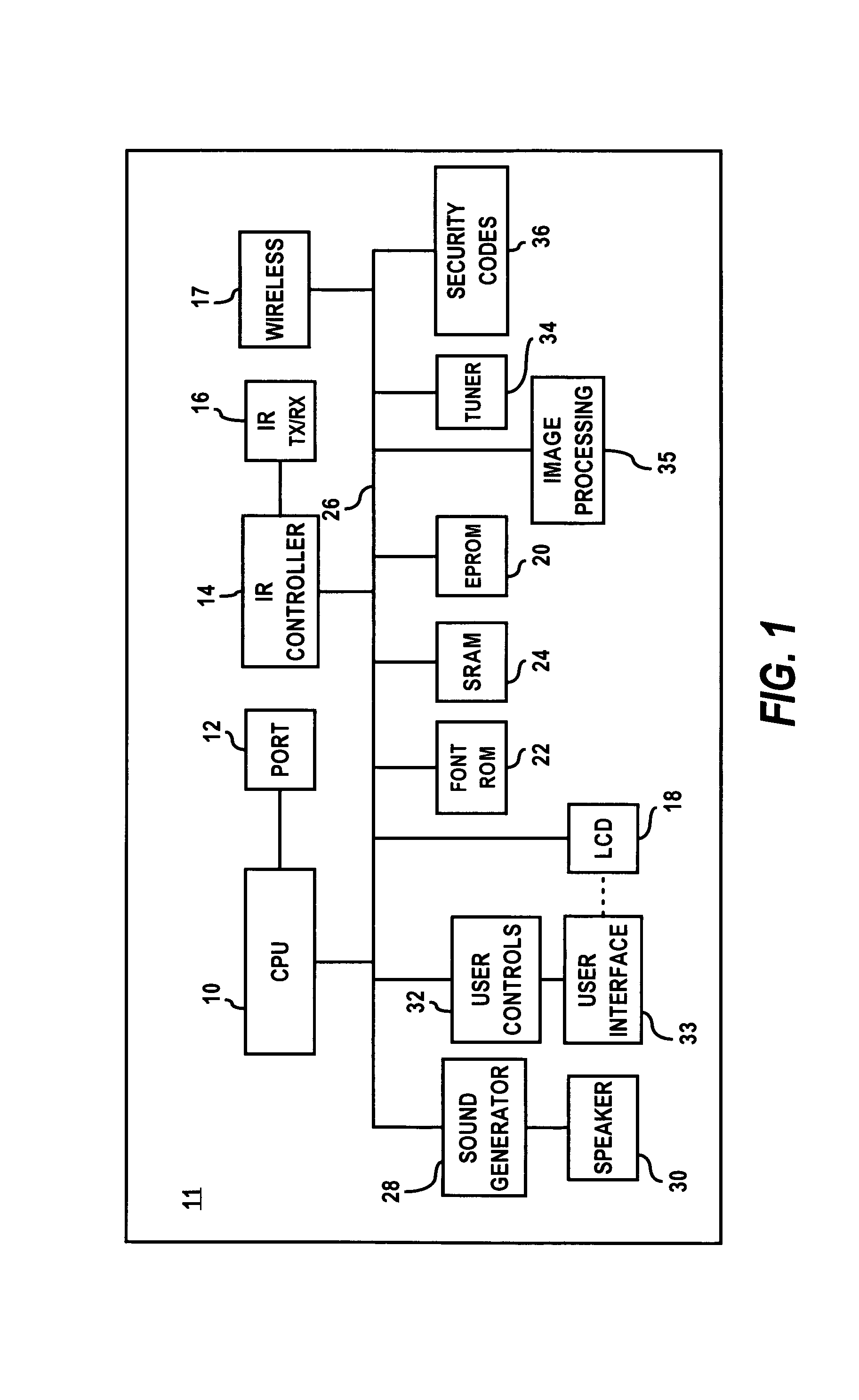
[0059]FIG. 1 depicts a schematic diagram illustrating a general hardware configuration of a hand held device 11, in accordance with an embodiment of the present invention. Those skilled in the art can appreciate, however, that other hardware configurations with less or more hardware and / or modules may be utilized in carrying out the methods and systems (e.g., hand held device 11) of the present invention, as may be further described herein. CPU 10 of hand held device 11, performs as a main controller operating under the control of operating clocks supplied from a clock oscillator. CPU 10 may be configured as a 16-bit microprocessor. External pins of CPU 10 are generally coupled to an internal bus 26 so that it may be interconnected to respective components.

[0060]SRAM 24 can be configured as a writeable memory that does not require a refresh operation and can be generally utilized as a working area of CPU 10. SRAM (Static RAM) is generally a form of semiconductor memory (RAM) based o...


PUM


Abstract

Methods and systems for receiving and displaying venue-based data at hand held devices are disclosed herein. Data transmitted from one or more venue-based data sources may be received by at least one hand held device present within a venue, such as a sports stadium or concert arena. Such data can be processed for display on a display screen associated with the hand held device. The processed data may be then displayed on the display screen, thereby enabling a user of the hand held device to view venue-based data through the hand held device. Such venue-based data viewable through the hand held device within the venue may include real-time and instant replay video images and clips, advertising and promotional information, scheduling, statistical, historical and other informational data, or a combination thereof.

Description

CROSS-REFERENCE TO RELATED APPLICATIONS[0001]This application claims the benefit of U.S. Provisional Application Ser. No. 60 / 243,561, filed Oct. 26, 2000 by Luis M. Ortiz and Kermit D. Lopez, for “Providing Multiple Perspectives for a Venue Activity through an Electronic Hand Held Device.”BACKGROUND OF THE INVENTION[0002]1. Technical Field of the Invention[0003]The present invention is related to wireless electronic hand held devices, such as Personal Digital Assistants (PDAs), hand held televisions, and data-enabled wireless telephones. The present invention also relates to techniques for remotely delivering video-related data to hand held devices. In addition, the present invention relates to techniques for providing increased viewing opportunities for audiences in venue environments, such as stadiums and concert arenas. Additionally, the present invention relates to wireless video data transmission to hand held devices.[0004]2. Description of the Related Art[0005]Most modern stad...

Claims


Application Information

Patent Timeline
IPC IPC(8): H04M1/00H04B1/38H04N5/232H04N7/173
CPCH04N7/173H04N7/17318H04N21/21805H04N21/2187H04N21/2347H04N21/2381H04N21/25816H04N21/25833H04N21/25841H04N21/41407H04N21/4181H04N21/4405H04N21/47202H04N21/6131H04N21/6181H04N23/661H04N23/631H04N23/698
Inventor ORTIZ, LUIS M.LOPEZ, KERMIT D.
Owner FRONT ROW TECH
Why Eureka
Try Eureka