Diagnostic system for a data acquisition system

Active Publication Date: 2006-12-12
GENERAL ELECTRIC CO
View PDF11 Cites 2 Cited by
  • Summary
  • Abstract
  • Description
  • Claims
  • Application Information

AI Technical Summary

Benefits of technology

[0007]One advantage of the invention is that the system may be accessed remotely. That is, the present invention may be accessed through an internet browser when the data acquisition system is coupled to a network. Such systems are particularly useful for complex systems that are

Problems solved by technology

Sorting through such a vast amount of data is difficult.
The

Method used


Image

  • Diagnostic system for a data acquisition system
  • Diagnostic system for a data acquisition system
  • Diagnostic system for a data acquisition system

Examples


Example

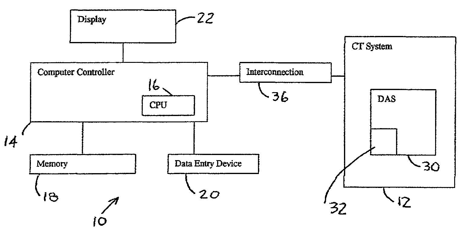
[0013]In the following figures the same reference numerals will be used to illustrate the same components. The following description is provided with respect to a computed tomography (CT) machine, however, those skilled in the art will recognize various applications for the diagnostic system described herein.

[0014]Referring now to FIG. 1, a diagnostic system 10 is illustrated coupled to a CT system 12. Diagnostic system 10 includes a computer controller 14 that is preferably microprocessor-based and thus has a CPU 16 therein. Computer controller 14 has a memory 18, a data entry device 20, and a display 22. Memory 18 may be various types of memory including RAM or ROM or hard disk, floppy disk, CD, or DVD. Data entry device 20 may be various types of data entry devices including a keyboard, touch screen, or other type of device. Display 22 is preferably a monitor and may include a flat panel or other type of monitor.

[0015]CT system 12 is illustrated as simply having a data acquisitio...


PUM


Abstract

A diagnostic system for a data acquisition system includes a computer controller that is coupled to the data acquisition system. A display device is coupled to the computer controller. The computer controller receives data from the data acquisition system and generates a screen display corresponding to an architectural representation of the data acquisition system. The controller generates screen indicia corresponding to a location of a problem on the architectural representation.

Description

BACKGROUND OF INVENTION[0001]The present invention relates generally to data acquisition systems, and more particularly, to a diagnostic system for a data acquisition system.[0002]Diagnostic systems typically are used to test the operation of the system during manufacturing and the functioning of the system in operation. Typical diagnostic systems perform tests and provide various test data. The test data is then analyzed by the technician to determine the source of the problem.[0003]Complex systems such as computed tomography (CT) type systems include a number of controlling circuit cards. One example of the amount of data provided in such a system is that fifty critical to quality (CTQ) characteristics may be tested in a complete test. Nearly 13,000 data points per CTQ may be obtained in such systems. Sorting through such a vast amount of data is difficult. Therefore, pinpointing the source of errors is also difficult.[0004]Therefore, it would be desirable to provide a system to e...

Claims


Application Information

Patent Timeline
IPC IPC(8): G06F15/00G06F11/273
CPCG06F11/2294
Inventor SCHER, CLAUDEDELPLANQUE, JEAN MARCRAMAKRISHNAN, SUNDARANANTHAKRISHNAN, RAM
Owner GENERAL ELECTRIC CO
Why Eureka
Try Eureka