System and method for automatically mapping state elements for equivalence verification

a state element and automatic mapping technology, applied in the field of formal equivalence verification, can solve the problems of inability to validate mappings during functional simulations, difficult process of building bdds, and more difficult to verify the correct structure and functionality of circuits designed for these systems

Inactive Publication Date: 2006-12-12
INTEL CORP
View PDF11 Cites 6 Cited by
  • Summary
  • Abstract
  • Description
  • Claims
  • Application Information

AI Technical Summary

Problems solved by technology

With the increasing complexity and shorter development cycles of current digital systems, it has become more difficult to verify that circuits designed for these systems have the correct structure and functionality.
However, the process of building BDDs is very difficult because state element mappings are often unknown.
Without prior identification of such don't care conditions, such mappings can be invalidated during functional simulations.
As of the present time, attempts at automatic state mapping have been largely unsuccessful, in part because they have not appropriately accounted for the variety of state element contingencies described.
Moreover, manual state mapping currently requires as much as several days per functional circuit block.

Method used


Image

  • System and method for automatically mapping state elements for equivalence verification
  • System and method for automatically mapping state elements for equivalence verification
  • System and method for automatically mapping state elements for equivalence verification

Examples


Embodiment Construction

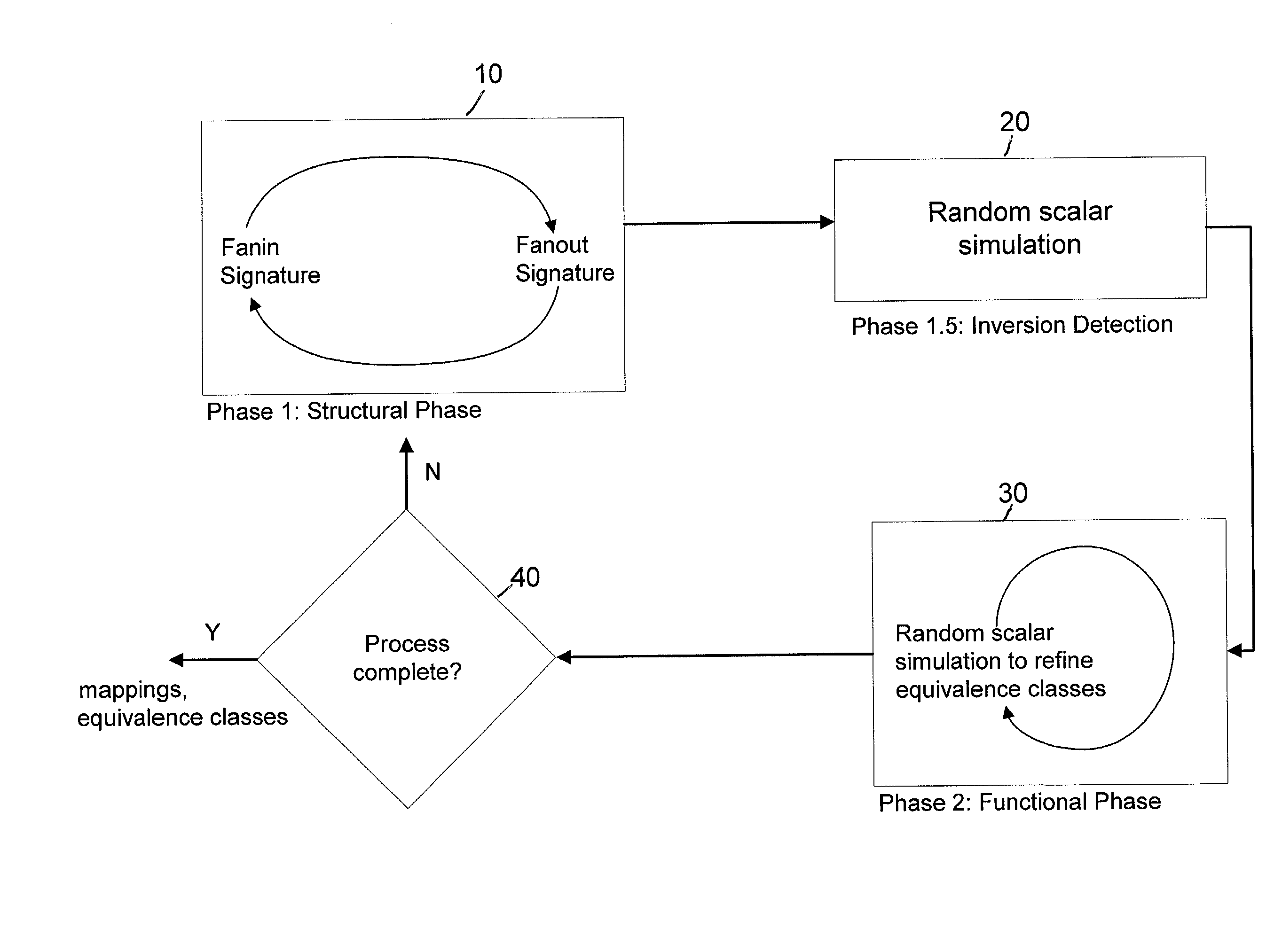
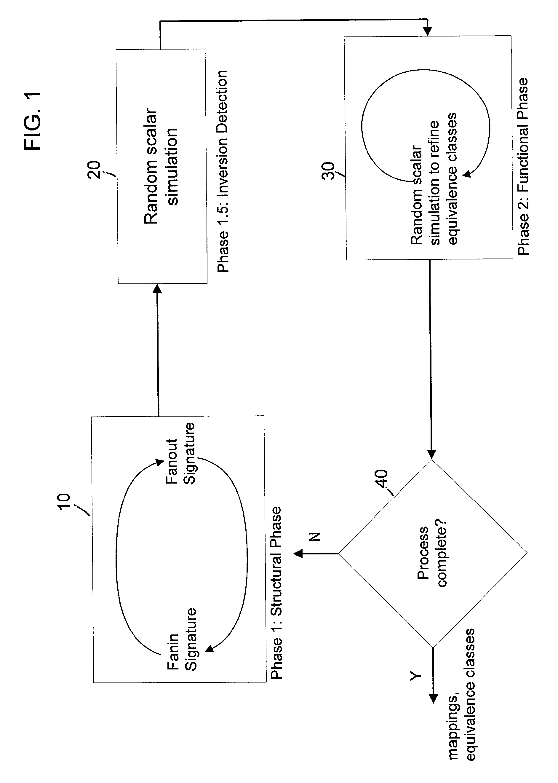
[0015]FIG. 1 illustrates a high-level flow diagram of an embodiment of the automatic state element mapping process according to the present invention. The state element mapping method is divided into three phases: a structural phase (Phase 1) 10, an inversion detection phase (Phase 1.5) 20 and a functional phase (Phase 2) 30. As indicated by the arrows connecting the phases in FIG. 1, the phases are performed in sequential order and may be repeated depending upon whether a threshold criterion is satisfied, indicating that the mapping process is complete.

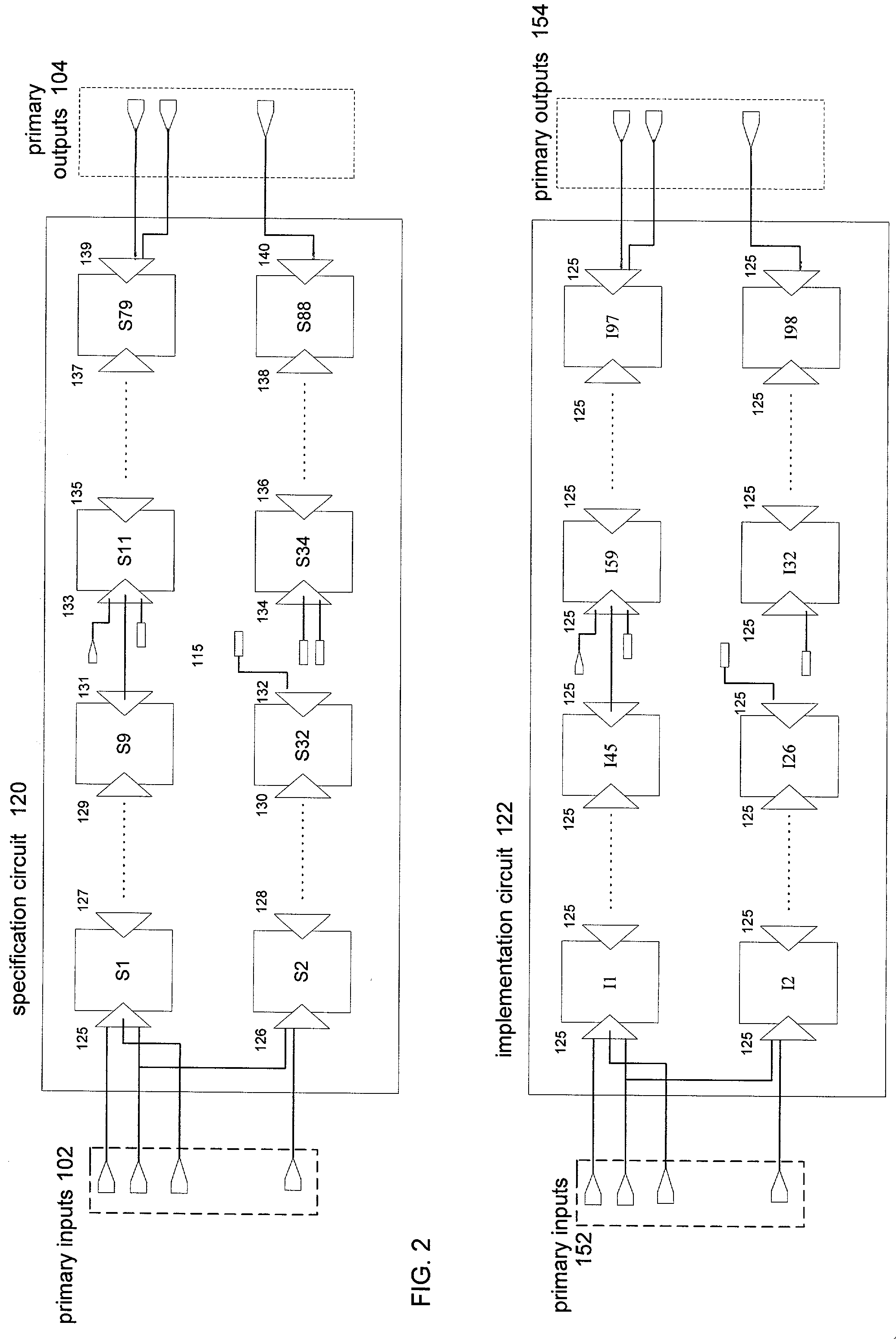
[0016]During the structural phase, Phase 1, partial fanin signatures of state elements of a first specification circuit are compared to partial fanin signatures of state elements of a second implementation circuit. A fanin signature of a particular element includes an alphabetically sorted list of the primary inputs and other state elements which provide inputs to that state element. Comparison of fanout signatures between state elem...


PUM


Abstract

A method for automatically mapping state elements between a first circuit and a second circuit is described. The method proceeds by comparing, in a structural phase, structural features of state elements in the first circuit to structural features of state elements in the second circuit for equivalence. Mappings between state elements of the first circuit and the second circuit are determined based on the comparison of structural features. “Don't care” input conditions are then accounted for prior to determination of functional features. During an inversion detection phase, the polarity of the mappings found in the prior structural phase are determined. A functional phase follows in which the functionality of state elements in the first circuit are compared to the functionality of state elements in the second circuit for equivalence using a three-valued random simulation and further mappings are determined based upon the functional comparison.

Description

FIELD OF THE INVENTION[0001]The present invention relates to formal equivalence verification for very large scale integrated (VLSI) circuits, and in particular relates to an algorithm for automatically mapping the state elements of two circuits that is executed to enable subsequent combinational formal equivalence verification of the circuits.BACKGROUND INFORMATION[0002]With the increasing complexity and shorter development cycles of current digital systems, it has become more difficult to verify that circuits designed for these systems have the correct structure and functionality. To assist in reducing errors and streamlining the development process, formal equivalence verification techniques are used to verify that circuit descriptions preceding and following a design step define the same functionality. Currently, the predominant formal equivalence verification technique is combinational verification, in which input and output logic cones of state elements (elements which store va...

Claims


Application Information

Patent Timeline
Patent Type & Authority Patents(United States)
IPC IPC(8): G06F17/50
CPCG06F17/504G06F30/3323
Inventor HOSKOTE, YATIN V.DORESWAMY, KIRAN B.
Owner INTEL CORP
Why Eureka
Try Eureka