Method for correcting a mask design layout

Inactive Publication Date: 2006-12-12
RGT UNIV OF MICHIGAN +1
View PDF3 Cites 233 Cited by
  • Summary
  • Abstract
  • Description
  • Claims
  • Application Information

AI Technical Summary

Benefits of technology

[0006]A method for performing a mask design layout resolution enhancement includes determining a level of correction for the design layout for a predetermined parametric yield with a minimum total correction cost. The design layout is corrected at the determined level of corre

Problems solved by technology

However, as minimum printed feature sizes continue to shrink, the wavelength of light used in modern lithography systems is no longer several times larger than the minimum line dimensions to be printed, e.g., today's 130 nm CMOS processes use

Method used


Image

  • Method for correcting a mask design layout
  • Method for correcting a mask design layout
  • Method for correcting a mask design layout

Examples


Embodiment Construction

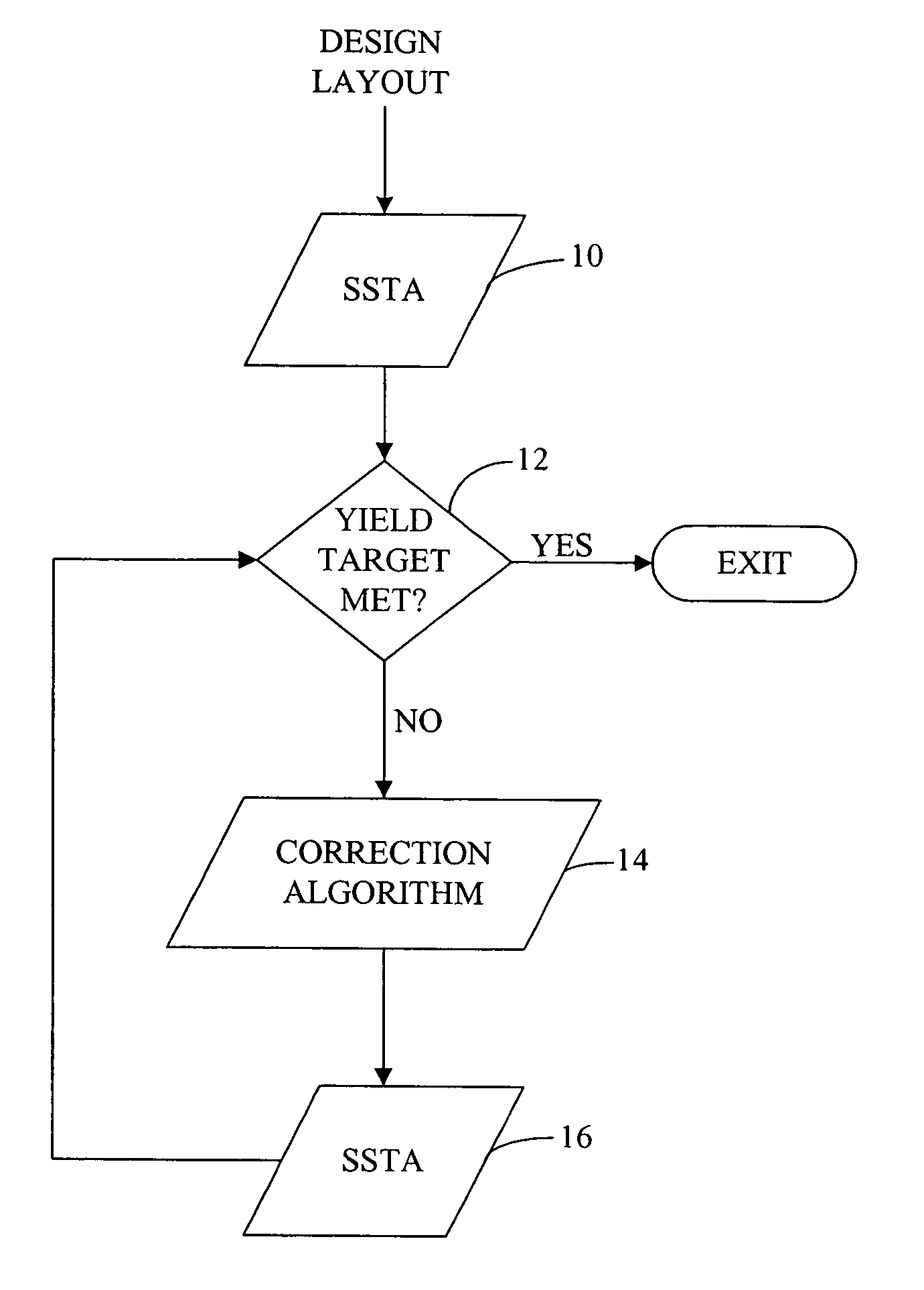
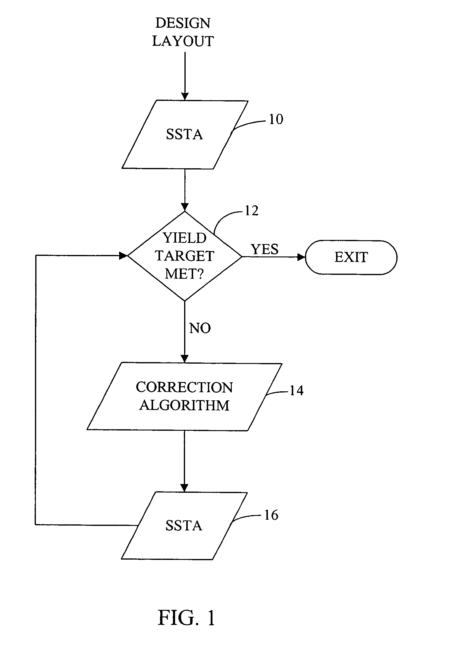
[0010]The present invention concerns reducing mask costs through process means. In accordance with one embodiment, the invention involves the use of various levels (e.g., moderate to aggressive) of resolution enhancement techniques (RETs), such as optical proximity correction (OPC), phase-shift masks (PSM) and sub-resolution assist features (SRAFs), for example, to limit mask complexity.

[0011]Many printed features in the layout of the mask design are not timing-critical and a larger degree of process variation may be tolerable for them. At the same time, a certain minimum level of process correction is required to ensure printability of the layout. Forward-annotating the design's functional information will permit less total correction to meet the parametric yield requirements. Less aggressive use of RET translates to lowered costs through reduced figure counts, shorter mask write times and higher mask yields.

[0012]In the present application, a “selling point” is defined as the circ...


PUM


Abstract

A method for performing a mask design layout resolution enhancement includes determining a level of correction for a mask design layout for a predetermined parametric yield with a minimum total correction cost. The mask design layout is corrected at a determined level of correction based on a correction algorithm if the correction is required. In this manner, only those printed features on the mask design layout that are critical for obtaining a desired performance yield are corrected, thereby reducing total cost of correction of the mask design layout.

Description

[0001]This Application claims the benefit of U.S. Provisional Application No. 60 / 450,051, filed Feb. 25, 2003.FIELD OF THE INVENTION[0002]The present invention is in the fields of optical lithography and integrated circuit fabrication.BACKGROUND OF THE INVENTION[0003]Consistent improvements in the resolution of optical lithography techniques have been a key enabler for continuation of Moore's Law. However, as minimum printed feature sizes continue to shrink, the wavelength of light used in modern lithography systems is no longer several times larger than the minimum line dimensions to be printed, e.g., today's 130 nm CMOS processes use 193 nm exposure tools. As a result, modem CMOS processes, for example, are operating in a sub-wavelength lithography regime. The International Technology Roadmap for Semiconductors (ITRS) offers projections on the requirements of next generation lithography systems and states that achieving aggressive microprocessor (MPU) gate lengths and highly contr...

Claims


Application Information

Patent Timeline
IPC IPC(8): G06F17/50
CPCG06F17/5068G06F30/39
Inventor KAHNG, ANDREW B.GUPTA, PUNEETSYLVESTER, DENNISYANG, JIE
Owner RGT UNIV OF MICHIGAN
Why Eureka
Try Eureka