Flywheel

Inactive Publication Date: 2006-12-19
LUK LAMELLEN & KUPPLUNGSBAU BETEILIGUNGS KG
View PDF6 Cites 4 Cited by
  • Summary
  • Abstract
  • Description
  • Claims
  • Application Information

AI Technical Summary

Benefits of technology

[0010]Another preferred exemplary embodiment is distinguished in that the sleeve is joined via a rivet to the flange. Joints using rivets require especially little structural space and can be easily produced.
[0011]Especially preferred is an exemplary embodiment that is distinguished in that the at least one buffer, at least in some areas, is elastically and / or plastically deformable, especially for producing the mating between the flange and the flywheel, especially a solid connection between the flange and the flywheel. In this way, the possibility is therefore intentionally provided of absorbing the forces that occur in the joining of the flange and flywheel through an intentional material deformation. Undesired deformations in areas, especially in the area of the friction surface, which must have an especially good manufacturing tolerance, can in this way be safely avoided.
[0013]In another exemplary embodiment of the invention, provision is made that the rib radially expands conically toward the friction surface. The rib is thus formed to be sturdier in the direction of the friction surface. This prevents elastic and / or plastic deformations that may occur in the area of the web from being transferred to the friction surface.
[0014]Moreover, the object of the present invention is achieved by a dual-mass flywheel having the features described in claim 10. It is distinguished in that the mounting surface has at least one buffer. This makes it possible to permit elastic and / or plastic deformations when producing the connection between the flange and the flywheel without this negatively affecting the characteristics of the friction surface.

Problems solved by technology

The alterations of the friction surface in this context can be so persistent / severe that its properties as a clutch are no longer acceptable.

Method used


Image

  • Flywheel
  • Flywheel
  • Flywheel

Examples


Embodiment Construction

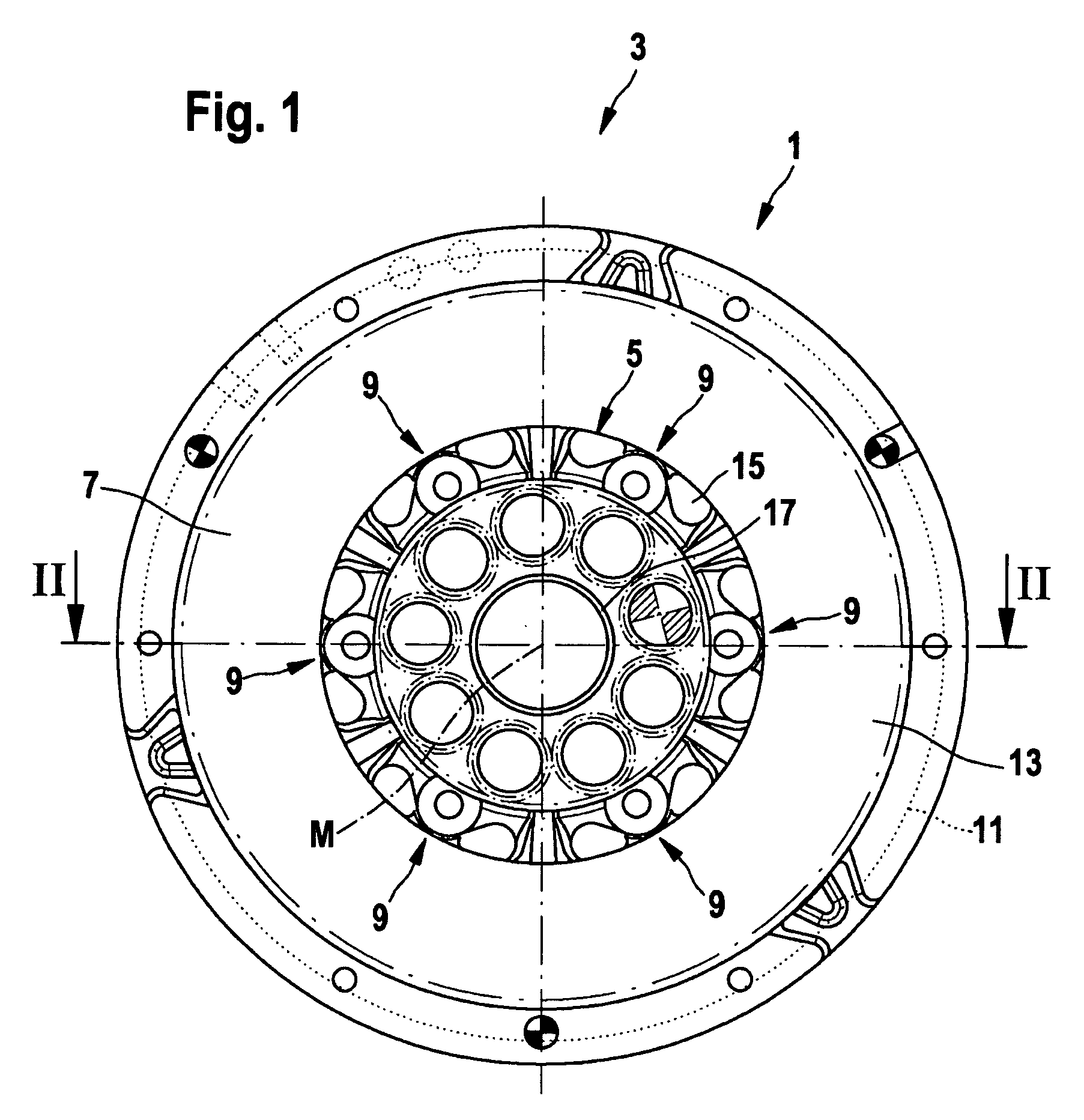
[0024]FIG. 1 shows a flywheel 1, which is in particular a part of a dual mass flywheel 3, having at least one mounting surface 5 and a friction surface 7.

[0025]Mounting surface 5 has at least one—in this case six—buffer(s) 9. The flywheel essentially has four annular function areas 11, 13, 15, 17. First function area 11 is used to link additional parts of a dry clutch (not shown here). Dry clutches are known, so this subject will not be dealt with further here. Second function area 13 is also a functional element of the dry clutch and includes friction surface 7 by which torque is transferable in a known way, especially via a frictional engagement. Third function area 15 has mounting surface 5 with buffers 9. Fourth function area 17 includes a friction bearing for the relative rotation of flywheel 1 along center axis M in relation to another rotating mass (not shown), which will be dealt with in detail in the description for FIGS. 4 and 5.

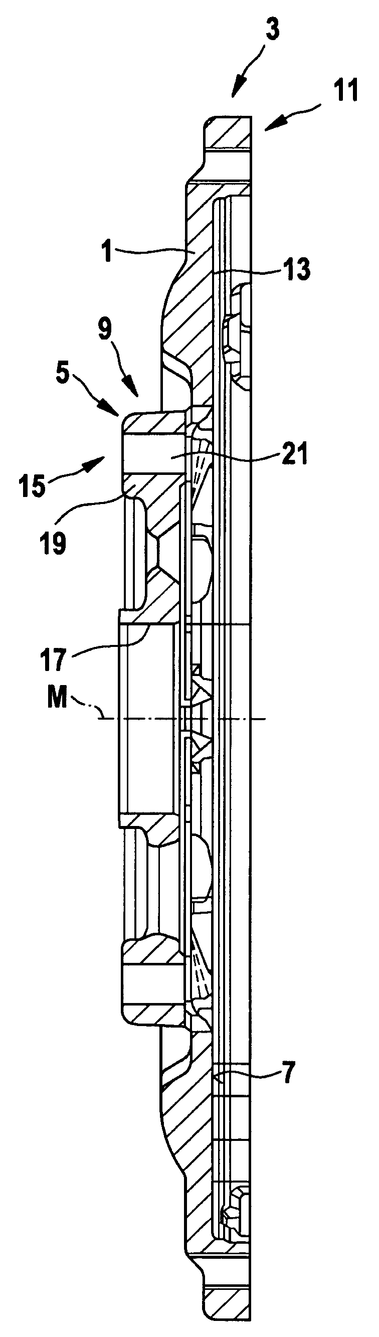
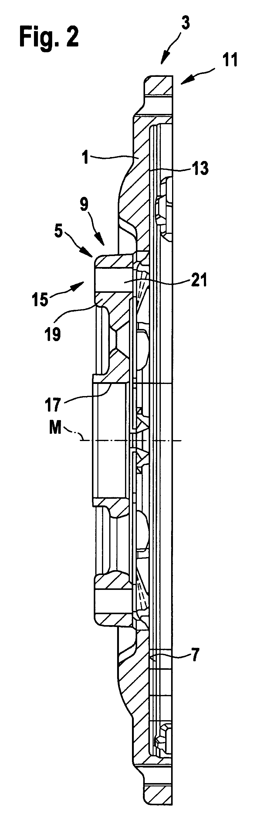
[0026]FIG. 2 shows a sectional illustration ...


PUM


Abstract

A flywheel, especially for a dual-mass flywheel, having a friction surface and a mounting surface that is able to mate with a flange. It is distinguished by at least one buffer for the buffering of the friction surface and the mounting surface.

Description

CROSS-REFERENCE TO RELATED APPLICATIONS[0001]This patent claims priority of German patent applications 102 60 120.8 and 103 10 045.8, which applications are incorporated herein by reference.BACKGROUND OF THE INVENTION[0002]This invention relates generally to a flywheel, especially for a dual-mass flywheel, with a friction surface and a mounting surface that is able to mate with a flange and a dual-mass flywheel with a primary rotating mass and a secondary rotating mass that has a flange and a flywheel with a friction surface and a mounting surface that is mated to the flange.[0003]Flywheels and dual-mass flywheels of the type addressed here are known. They are used for torsional vibration damping, especially in a drive train of a motor vehicle. Moreover, they are used to couple two units, especially an engine, preferably an internal combustion engine, to a drive unit, preferably a clutch and / or a transmission. The known flywheels have a friction surface, which is also called a runni...

Claims


Application Information

Patent Timeline
IPC IPC(8): F16C15/00F16F15/315F16D13/70F16F15/131F16F15/139F16F15/30F16F15/31
CPCF16D13/70F16F15/1397F16F15/13164Y10T74/2121
Inventor JACKEL, JOHANNMENDE, HARTMUTJUNK, ANDREAS
Owner LUK LAMELLEN & KUPPLUNGSBAU BETEILIGUNGS KG
Why Eureka
Try Eureka