Fish tape having electrical box locator circuit and method therefor

Inactive Publication Date: 2006-12-19
SWIFT RICHARD C
View PDF5 Cites 14 Cited by
  • Summary
  • Abstract
  • Description
  • Claims
  • Application Information

AI Technical Summary

Benefits of technology

[0006]In accordance with one embodiment of the present invention, it is an object of the present invention to provide an improved fish tap assembly.
[0007]It is another object of t

Problems solved by technology

A problem exists in that in many wire installations in new or existing buildings, the conduit pathway may be fairly long.
Furthermore, the electrical box/junction box may be hidden i

Method used


Image

  • Fish tape having electrical box locator circuit and method therefor
  • Fish tape having electrical box locator circuit and method therefor
  • Fish tape having electrical box locator circuit and method therefor

Examples


Embodiment Construction

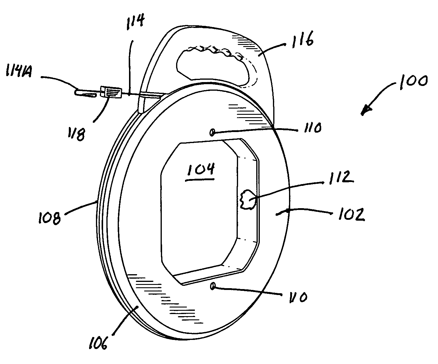
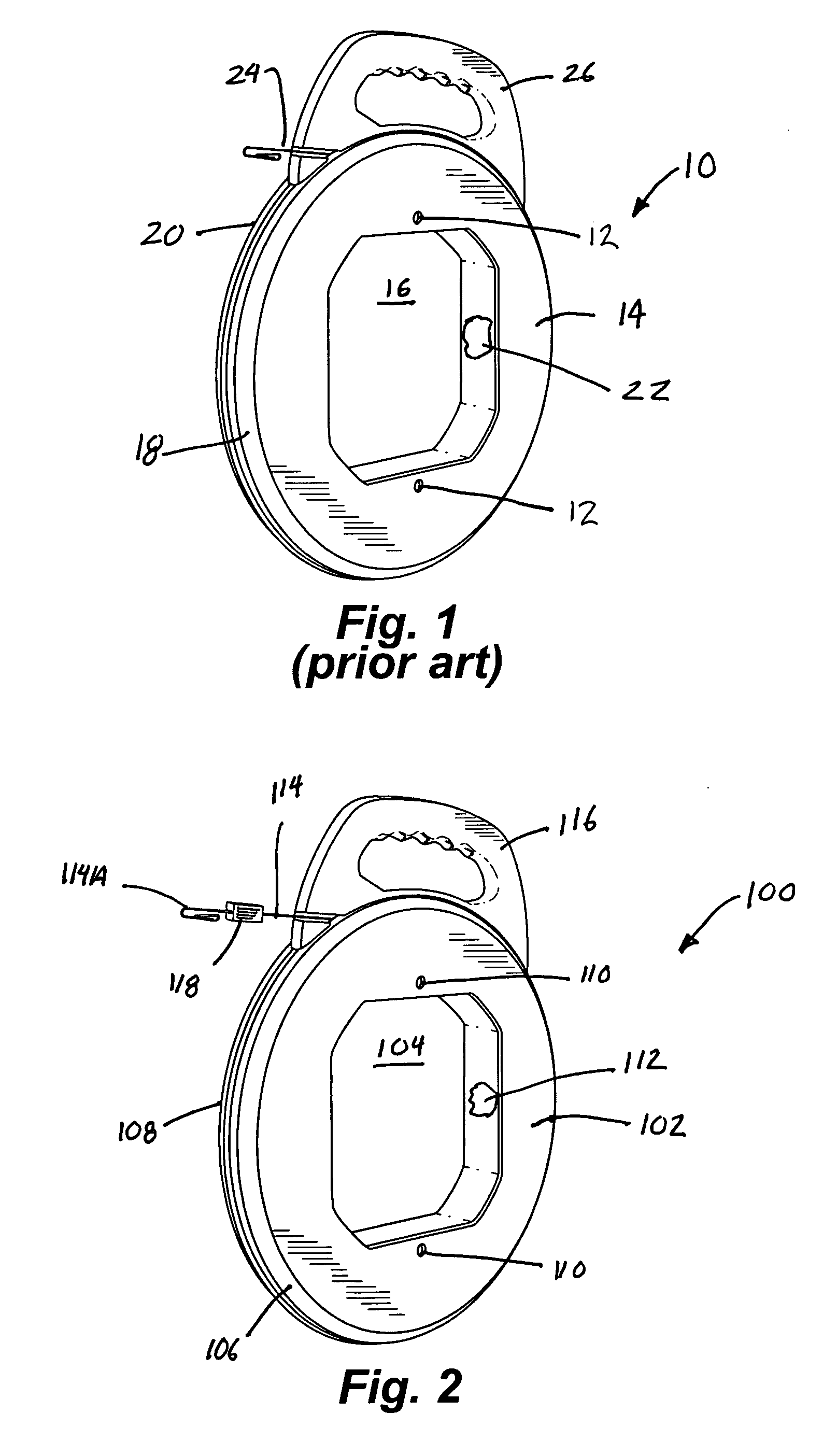
[0008]In accordance with one embodiment of the present invention a fish tape assembly is disclosed. The fish tape assembly has a fish tape. A housing is provided for storing the fish tape. A location indicator circuit is coupled to a first end of the fish tape. The location indicator circuit being used to send a location signal indicating a location of the first end of the fish tape.

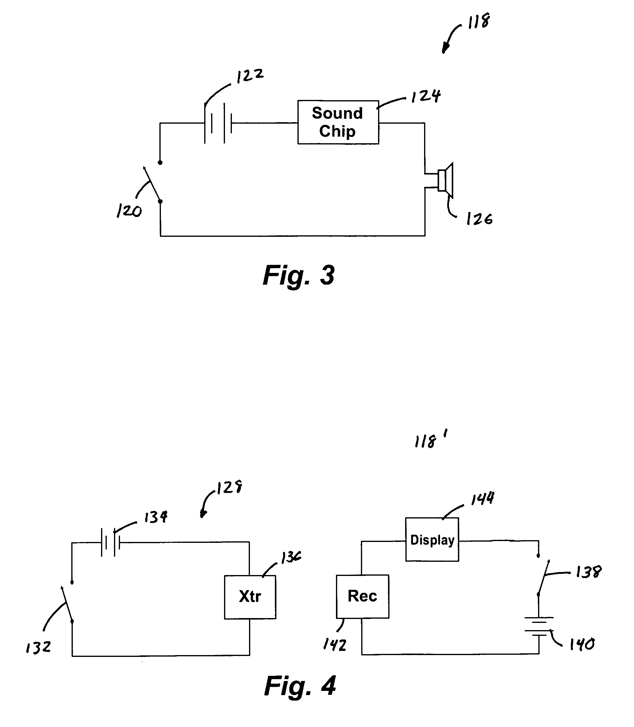
[0009]In accordance with another embodiment of the present invention a fish tape assembly is disclosed. The fish tape assembly has a fish tape. A housing is provided for storing the fish tape. The housing has a first outer shell. A second outer shell is coupled to the first outer shell to form a hollow interior section for storing the fish tape. A location indicator circuit is coupled to a first end of the fish tape to send a location signal indicating a location of the first end of the fish tape. The location indicator circuit has a sound chip for generating a location signal. A speaker is coupled to th...


PUM


Abstract

A fish tape assembly has a fish tape. A housing is provided for storing the fish tape. A location indicator circuit is coupled to a first end of the fish tape. The location indicator circuit being used to send a location signal indicating a location of the first end of the fish tape.

Description

FIELD OF THE INVENTION[0001]The present invention relates to electrical wire installation and, more specifically, to a fish tape device having a location circuit coupled thereto for helping an individual locate an electrical box located within a wall where the end of the fish tape is located.BACKGROUND OF THE INVENTION[0002]When installing electrical wire in a home or office building, a fish tape is generally used. A fish tape is an elongated wire member made of tempered spring steel, stainless steel, multi-stranded steel wire, nylon, or the like. The elongated wire member of the fish tape is rigid enough to be pushed through a conduit yet flexible enough to bend around corners or curves in the conduit. After the tape has been “fished” or threaded through a conduit, a wire or cable is attached to the end of the fish tape and the tape is pulled back through the conduit, drawing the wire with it to install the wire in the conduit.[0003]In general, when installing electrical wiring, th...

Claims


Application Information

Patent Timeline
IPC IPC(8): B66F3/00H02G1/08
CPCH02G1/085H02G11/02
Inventor SWIFT, RICHARD C.
Owner SWIFT RICHARD C
Why Eureka
Try Eureka