Scalpel blade holder and scalpel

a scalpel and blade technology, applied in the field of scalpel blade holders and scalpels, can solve the problems of unnecessary time delays and concentration loss

Inactive Publication Date: 2006-12-19
SIS SURGICAL INSTR SYST
View PDF8 Cites 36 Cited by
  • Summary
  • Abstract
  • Description
  • Claims
  • Application Information

AI Technical Summary

Benefits of technology

[0003]It is an object of the present invention to propose a new scalpel and a new scalpel blade holder which do not have the drawbacks of the state of the art and which make it possible in particular to align a scalpel blade without eye contact.
[0004]The above-mentioned objects are achieved through the present invention in particular in that the handle region of the scalpel blade holder comprises three lateral faces which are disposed such that a cross-section with a substantially triangular envelope results for the handle region, and at least one of the lateral faces is provided with tactile identifying features. The triangular envelope of the cross-section of the handle region facilitates a proper holding of the scalpel blade holder between middle finger, thumb and index finger, the scalpel blade holder and thus the scalpel fixed thereto being able to assume only three different rotational states about the center axis of the handle region of the scalpel blade holder, with respect to the fingers. Since at least one of the three lateral faces of the handle region is provided with tactile identifying features, the user can thus determine the alignment of the scalpel blade holder and of the scalpel fixed thereto via his fingers by means of his sense of touch, without having to make eye contact with the scalpel or with the scalpel blade holder for this purpose. In other words, without looking at the scalpel blade holder or at the scalpel blade, the user can identify, via his sense of touch, the alignment of the scalpel blade with a view to its rotation about the center axis of the handle region of the scalpel blade holder. The triangular envelope of the cross-section of the handle region has moreover the advantage that the scalpel blade holder in laid down state does not roll away and the scalpel fixed thereto does not become damaged.
[0005]In a preferred embodiment variant, the envelope of the cross-section of the handle region has substantially the form of an arc triangle and the corners of the envelope of the cross-section of the handle region are rounded. The arctriangular shape makes possible a better grip between middle finger, thumb and index finger. The rounded corners also contribute to a better grip, and in addition prevent the user from hurting himself on the corners or damaging protective gloves.

Problems solved by technology

To align the scalpel blade, the user must therefore glance away from the place where the operative procedure is supposed to be carried out, which is inconvenient, especially when microscopes or magnifying glasses are being used, and which leads to unnecessary time delays and losses of concentration.

Method used


Image

  • Scalpel blade holder and scalpel
  • Scalpel blade holder and scalpel
  • Scalpel blade holder and scalpel

Examples


Embodiment Construction

[0021]In FIGS. 1 to 7 same components corresponding to one another are designated by the same reference numerals.

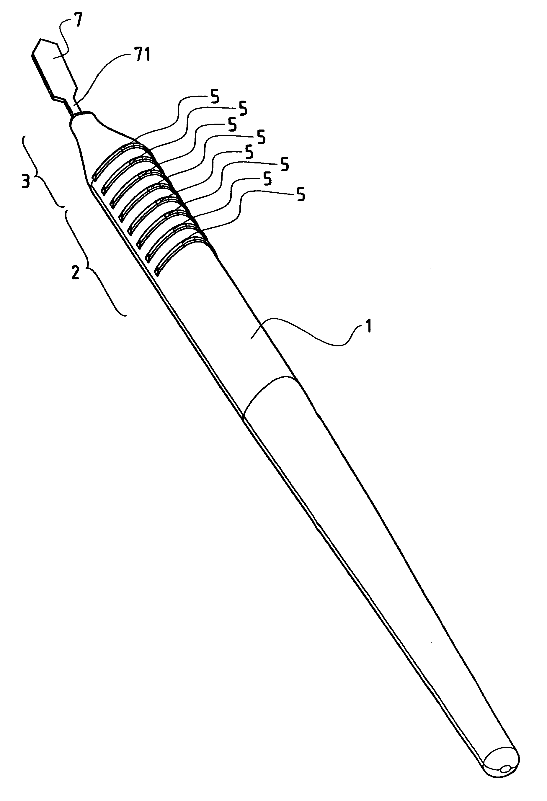
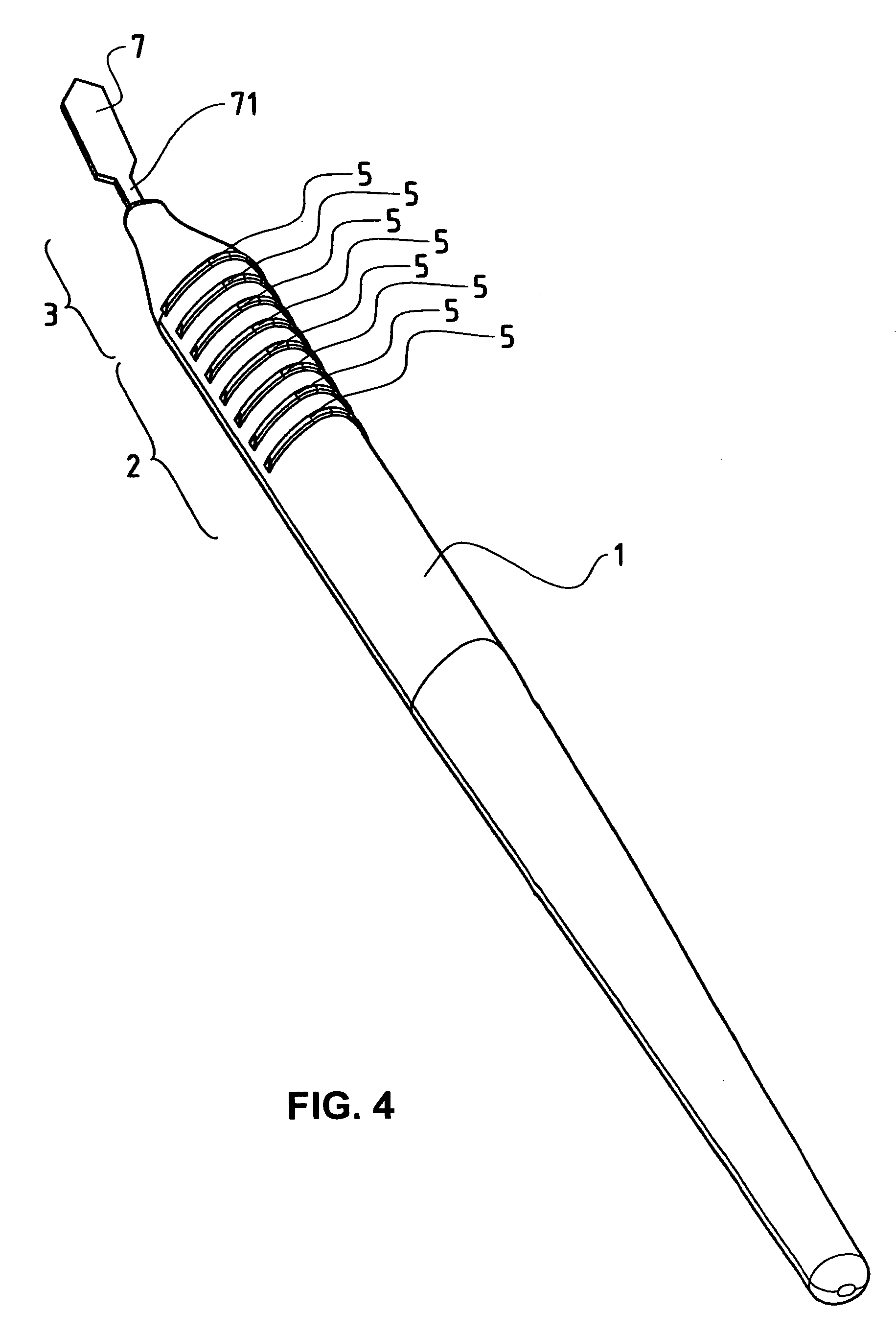
[0022]Shown in FIG. 4 is a three-dimensional view of a scalpel with a scalpel blade holder 1 and a scalpel blade 7 fixed thereon. The scalpel blade holder 1 has a handle region 2 and an end region 3 tapering from the handle region 2. The handle region 2 has tactile identifying features in the form of protrusions 5.

[0023]As shown in FIG. 5, the end region 3 has a bore 4, in which the attachment cylinder 71 of the scalpel blade 7 (see FIG. 4) is insertable for attaching the scalpel blade 7. To attach the scalpel blade 7, the attachment cylinder 71 is glued, bonded or welded in the bore 4. The attachment can also take place by means of press fit. The scalpel blade holder 1 can also be molded around the attachment 71 in an injection molding process; in so doing the attachment cylinder 71 preferably has structural elements on its surface.

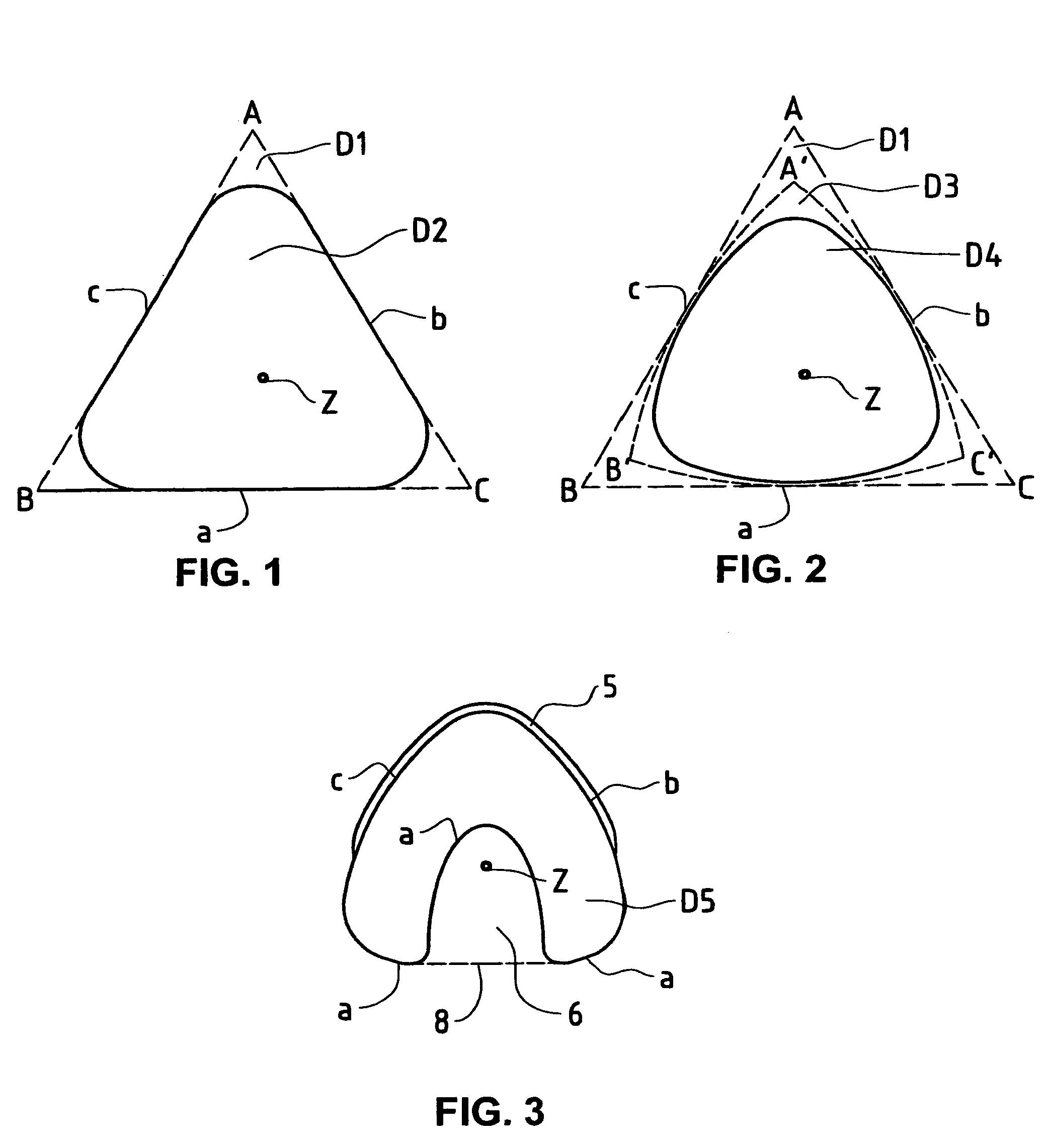
[0024]Shown in FIGS. 1, 2 and 3 are sec...


PUM


Abstract

Proposed are a scalpel blade holder and a scalpel with a scalpel blade holder, which make it possible for a user to determine the rotation of the scalpel about the center axis of the scalpel blade holder without eye contact with the scalpel or with the scalpel blade. The handle region of the scalpel blade holder comprises three lateral faces which are disposed such that a cross-section with a substantially triangular envelope results for the handle region. The envelope of the cross-section of the handle region has substantially the form of an arc triangle whose corners are rounded. A plurality of tactile identifying features are designed as protrusions in the form of ribs extending over two of the lateral faces and running crosswise to the longitudinal axis of the scalpel blade holder. One of the tactile identifying features is designed as a recess, and is disposed on the remaining third lateral face, and extends over part of the length of the scalpel blade holder. By means of his sense of touch, the user can determine the alignment of the scalpel blade with regard to its rotation about the center axis of the scalpel blade holder.

Description

TECHNICAL FIELD[0001]The present invention relates to a scalpel blade holder and a scalpel. The invention relates in particular to a scalpel blade holder and a scalpel having a handle region and means of attaching a scalpel blade.BACKGROUND ART[0002]Conventional scalpel blade holders and scalpels have means for detachable or non-detachable fixing of scalpel blades and have a handle region which makes it possible for the user to hold the scalpel, or respectively the scalpel blade holder, with the fingers of one hand. When using scalpels and scalpel blade holders, the user must make sure by means of a glance that he has the instrument in his fingers in such a way that the scalpel blade is correctly aligned and the cutting edge of the scalpel blade faces in the desired direction. To align the scalpel blade, the user must therefore glance away from the place where the operative procedure is supposed to be carried out, which is inconvenient, especially when microscopes or magnifying glas...

Claims


Application Information

Patent Timeline
Patent Type & Authority Patents(United States)
IPC IPC(8): A61B17/32A61B17/00
CPCA61B17/3213A61B2017/00455A61B2017/0046A61B2019/446A61B90/94
Inventor ZIEMER, FRANK
Owner SIS SURGICAL INSTR SYST
Why Eureka
Try Eureka