Imaging apparatus with interchangeable lens apparatus, the lens apparatus having a memory for storing optical performance data of the lens apparatus

a technology of lens apparatus and memory, applied in the field of optical instruments, can solve the problems of difficult adjustment of light quantity, degraded image quality, and high image quality, and achieve the effect of efficient recording

Inactive Publication Date: 2006-12-19
CANON KK
View PDF14 Cites 32 Cited by
  • Summary
  • Abstract
  • Description
  • Claims
  • Application Information

AI Technical Summary

Benefits of technology

[0085]Accordingly, an object of the present invention is to enable appropriate images to be efficiently recorded on the side of the imaging apparatus according to various performances of the imaging lens apparatus.

Problems solved by technology

When the aperture diameter of the stop is reduced, a problem arises in that image quality is degraded by diffraction.
However, when the usable aperture range is limited like this, it is difficult to adjust the light quantity so as to be optimum only by the stop for a wide range of brightness of the actual field.
Moreover, when a lens always satisfying the highest performance of the CCD is prepared, since it is necessary that sufficient MTF be obtained even when the system is designed with a CCD having the highest pixel size in mind, even users not requiring such high image quality are obliged to use a lens of unnecessarily high performance (in many cases, the lens size increases as the MTF increases).

Method used


Image

  • Imaging apparatus with interchangeable lens apparatus, the lens apparatus having a memory for storing optical performance data of the lens apparatus
  • Imaging apparatus with interchangeable lens apparatus, the lens apparatus having a memory for storing optical performance data of the lens apparatus
  • Imaging apparatus with interchangeable lens apparatus, the lens apparatus having a memory for storing optical performance data of the lens apparatus

Examples


first embodiment

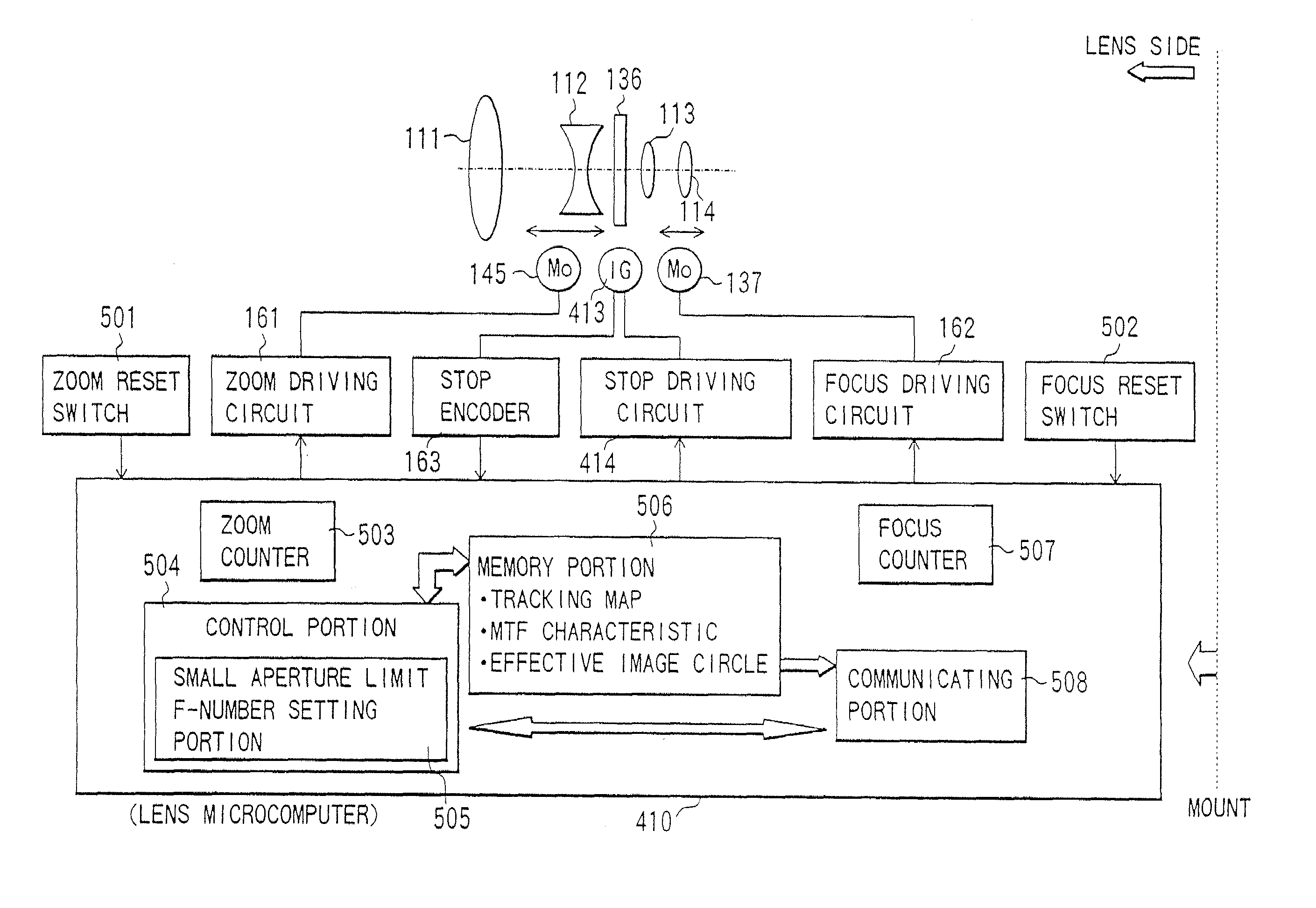
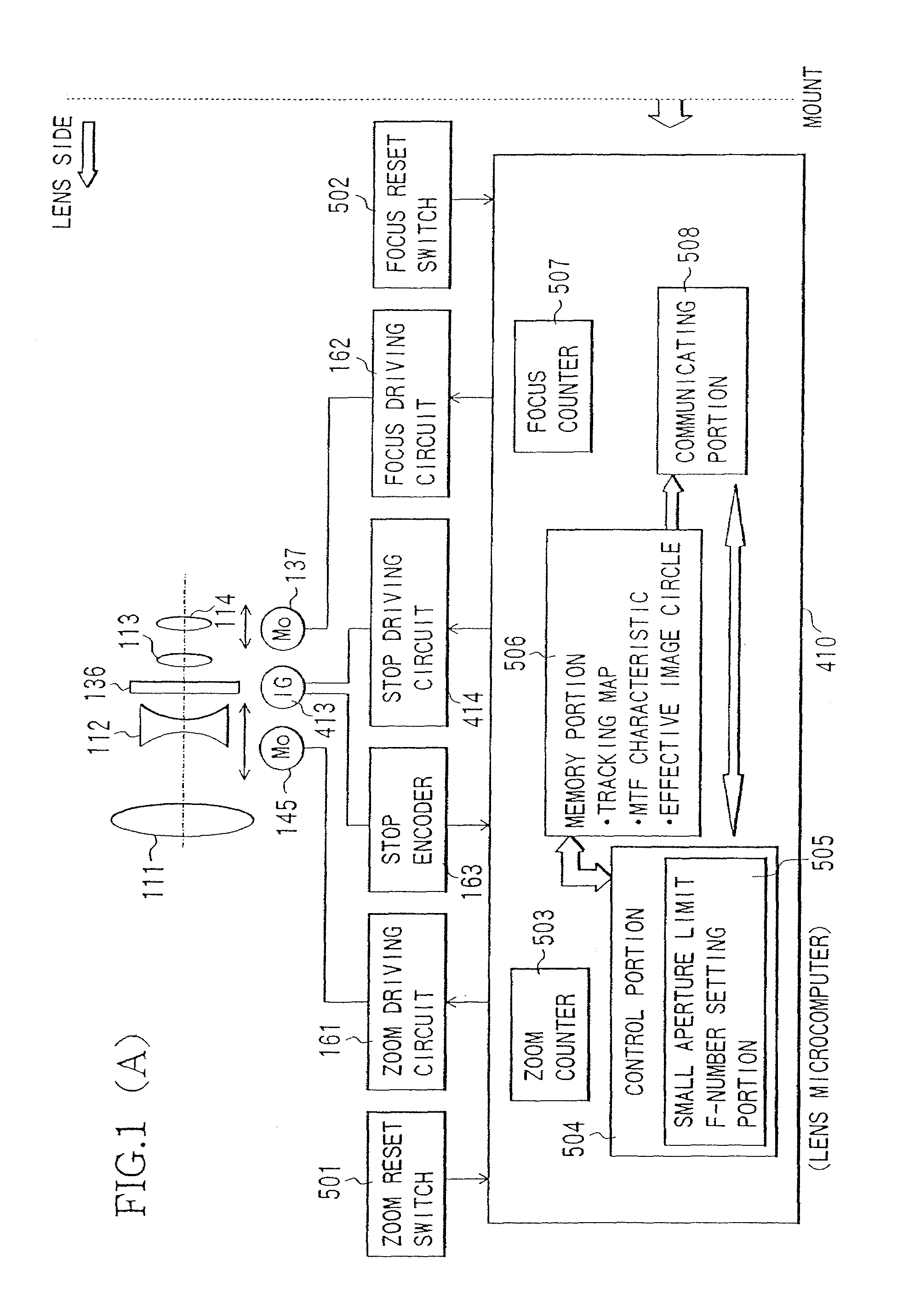
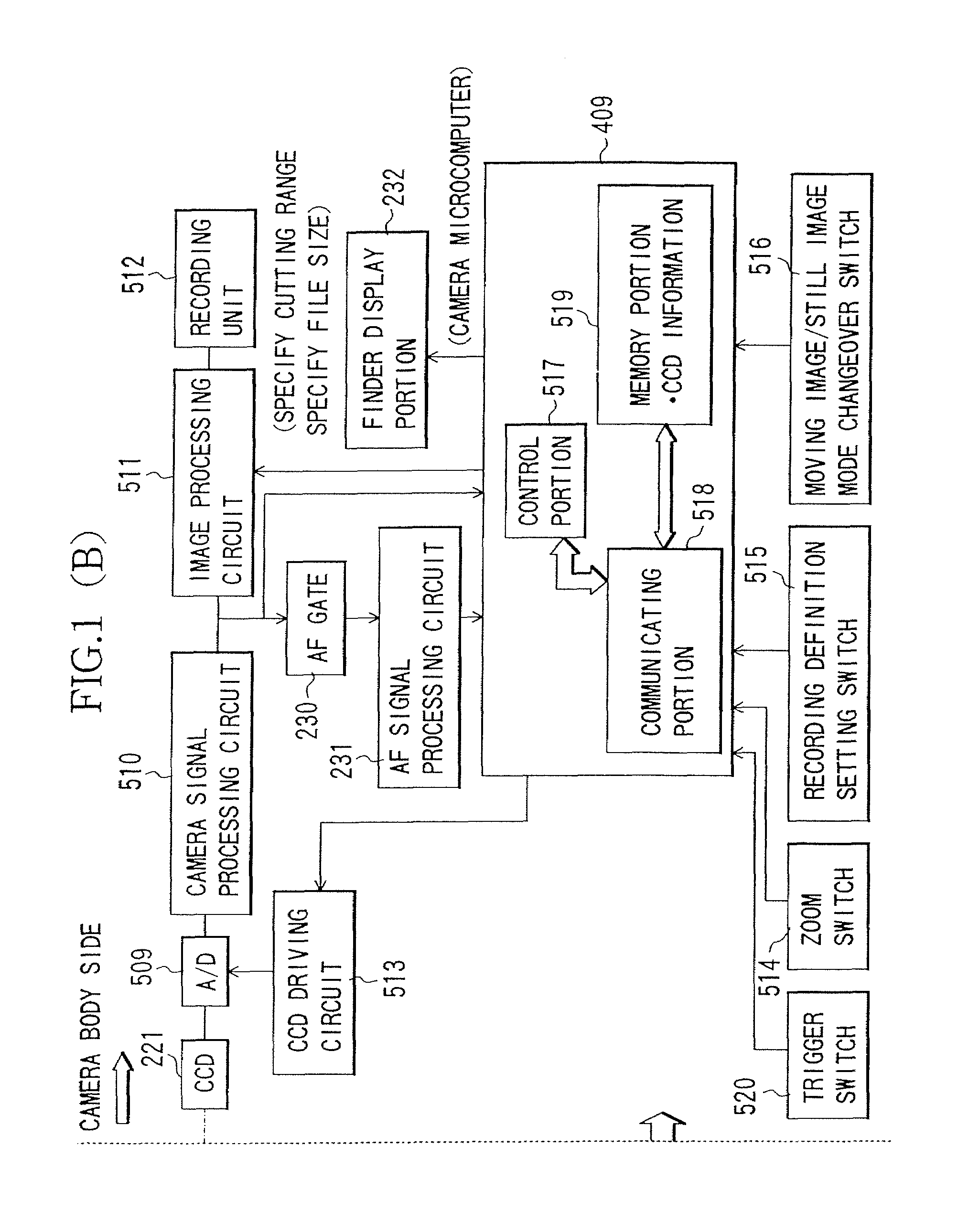
[0112]FIGS. 1(A) and 1(B) show the structure of a principal part of an imaging system according to the present invention. This imaging system comprises a camera body (imaging apparatus) and a shooting lens interchangeable for the camera body.

[0113]First, the structure on the shooting lens side will be described. In FIG. 1(A), reference numerals 111 through 114 shows four lens components included in the shooting lens. The shooting lens of the present embodiment is a zoom lens system having four lens components: from the subject side, a positive lens component, a negative lens component, a positive lens component and a positive lens component. However, the shooting lens apparatus of the present invention is not limited to the shooting lens of this lens component structure.

[0114]The lens component 111 is a stationary front lens component. The lens component 112 is a variator lens component changing the focal length (performing zooming) by changing its position in the direction of the o...

second embodiment

[0156](Second Embodiment)

[0157]While in the first embodiment, the MTF associated information based on the MTF characteristic data of the shooting lens side is transmitted to the camera body side and based on this information, the image can be recorded in a minimum file size in a range where the lens performance can be delivered to the maximum on the camera body side, in the present embodiment, information associated with the effective image circle of the shooting lens (hereinafter, referred to as effective image circle associated information) is transmitted from the lens side to the camera body side.

[0158]In the present embodiment, the effective image circle data of the shooting lens is stored in the memory portion 506 of the lens microcomputer 410 shown in FIG. 1(A). This data is stored as values of a plurality of effective image circles corresponding to the focal lengths and the F-numbers of the shooting lens.

[0159]The lens microcomputer 410 transmits information associated with t...

third embodiment

[0174](Third Embodiment)

[0175]FIGS. 4(A) and 4(B) shows the structure of an imaging system according to a third embodiment of the present invention. In the imaging system of the present embodiment, members the same as those of the imaging system of the first embodiment are designated by the same reference numerals as those of the first embodiment and will not be described again.

[0176]In the present embodiment, a vibration sensor 530 is provided on the camera body side. A signal responsive to a vibration of the camera body output from the vibration sensor 530 is taken into the camera microcomputer 409.

[0177]As the vibration sensor 530, a piezoelectric vibrating gyro or the like is used. In the present embodiment, two vibration sensors, one for detecting a rotation component in the longitudinal (pitch) direction and one for detecting a rotation component of the lateral (yaw) direction are provided.

[0178]According to the conventional electronic vibration compensation, image blur is com...


PUM


Abstract

An optical apparatus including an imaging apparatus and a lens apparatus each having a communicating portion performing communications is disclosed. The optical apparatus is provided with: an imaging optical unit; a memory in which information of an optical performance of the imaging optical unit is stored; an image pickup device imaging a subject image from the imaging optical unit; an imaging controller changing an information size of image information from the image pickup device; and a lens controller connected to the imaging controller through the communicating portions and performing communications with the imaging controller. The lens controller takes out the information of the optical performance from the memory in response to an instruction from the imaging controller, and transmits the information to the imaging controller through the communicating portions. The imaging controller changes the information size of the image information in accordance with the information of the optical performance from the lens controller.

Description

BACKGROUND OF THE INVENTION[0001]1. Field of the Invention[0002]The present invention relates to an optical apparatus, and more specifically, to an optical apparatus comprising an imaging apparatus having an image pickup device, a lens apparatus interchangeably attached to an imaging apparatus, and the imaging apparatus to which the lens apparatus is attached.[0003]2. Description of the Related Art[0004]A zoom lens system conventionally used for video cameras will be described.[0005]Examples of zoom lens systems for video cameras include a four-component lens system comprising from the subject side a stationary positive lens component, a movable negative lens component, a stationary positive lens component and a movable positive lens component.[0006]FIGS. 8(A) and 8(B) show the lens barrel structure of a general four-component zoom lens system. FIG. 8(B) shows a cross section taken on the line A—A of FIG. 8(A).[0007]The four lens components 201a to 201d constituting this zoom lens s...

Claims


Application Information

Patent Timeline
Patent Type & Authority Patents(United States)
IPC IPC(8): H04N5/225G03B7/095G02B7/02G02B7/10G03B5/00G03B7/20G03B17/14G03B17/18G03B19/02H04N5/232
CPCG02B7/102H04N5/23209H04N5/23296H04N23/663H04N23/69
Inventor KANEDA, NAOYA
Owner CANON KK
Why Eureka
Try Eureka