Multiple-sampling circuit for measuring reflected voltage and discharge time of a transformer

a transformer and voltage measurement technology, applied in the direction of dc-dc conversion, power conversion systems, instruments, etc., can solve the problem that the prior art cannot measure the voltage signal accurately of the transformer, and achieve the effect of soft switching

Active Publication Date: 2006-12-19
FAIRCHILD SEMICON CORP
View PDF2 Cites 33 Cited by
  • Summary
  • Abstract
  • Description
  • Claims
  • Application Information

AI Technical Summary

Benefits of technology

[0005]An object of the present invention is to provide a precise sampling circuit in a switching controller of a power supply to measure a voltage signal and a discharge time of a transformer. An output voltage and an output current are regulated without an optical-coupler and a secondary-side regulator. In addition, the discharge time of the transformer is an important factor for quasi-resonant power converters to synchronize with the valley voltage and achieve soft switching.

Problems solved by technology

In order to reduce the device counts and do without a secondary-side feedback circuit, a primary-side control technique has been disclosed in U.S. Pat. No. 4,302,803 “Rectifier-Converter Power Supply with Multi-Channel Flyback Inverter”, issued to Randolph D. W. Shelly. However, foregoing prior art cannot measure an accuracy voltage signal from the transformer.

Method used


Image

  • Multiple-sampling circuit for measuring reflected voltage and discharge time of a transformer
  • Multiple-sampling circuit for measuring reflected voltage and discharge time of a transformer
  • Multiple-sampling circuit for measuring reflected voltage and discharge time of a transformer

Examples


Embodiment Construction

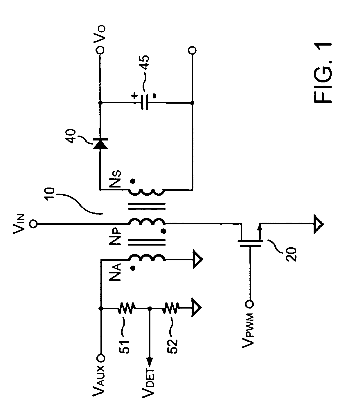
[0021]FIG. 1 shows a switching circuit, comprising a transformer 10 having an auxiliary winding NA, a primary winding NP, and a secondary winding NS. The primary winding NP is coupled to an input voltage VIN. A voltage divider formed by resistors 51 and 52 is connected to the auxiliary winding NA for obtaining a reflected voltage signal VDET from a voltage signal VAUX at the auxiliary winding NA. In order to regulate an output voltage VO and an output current IO of the switching circuit, a switching signal VPWM switches the transformer 10 via a switch, such as a transistor 20.

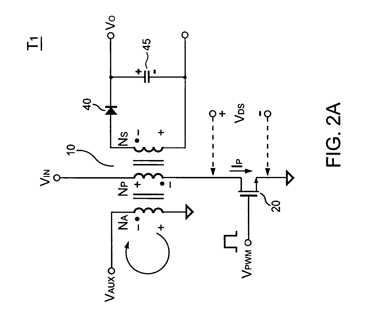
[0022]Referring to FIG. 1 and FIG. 2A, when the switching signal VPWM becomes on (logic-high), a primary-side switching current IP is generated accordingly to store energy into the transformer 10. Various waveforms in the switching circuit in this stage are shown during a period T1 in FIG. 3. A peak value IP1 of the primary-side switching current IP can be given by,

[0023]IP1=VINLP×TON(1)

where LP is the inductan...


PUM


Abstract

A multiple-sampling circuit is proposed for measuring a voltage signal and a discharge time of a transformer. Sampling signals are used for generating hold voltages by alternately sampling the reflected voltage from the transformer. A buffer amplifier generates a buffer voltage from the higher voltage of hold voltages. A sampling switch periodically conducts the buffer voltage to produce a voltage-feedback signal. The voltage-feedback signal is proportional to an output voltage of the switching circuit. A threshold signal added to the reflected voltage signal produces a level-shift reflected signal. A discharge-time signal is generated as the switching signal is disabled. The discharge-time signal is disabled once the level-shift signal is lower than the voltage-feedback signal. The pulse width of the discharge-time signal is therefore correlated to the discharge time of the transformer. The sampling signals are enabled to generate hold voltages only when the discharge-time signal is enabled.

Description

BACKGROUND OF THE INVENTION[0001]1. Field of the Invention[0002]The present invention relates to a control circuit for a power supply, and more specifically relates to a switching controller for a switching mode power supply.[0003]2. Description of Related Art[0004]Power supplies have been widely used to provide regulated output voltages. For safety, an off-line power supply must provide galvanic isolation between its primary side and secondary side. An optical-coupler and a secondary-side regulator are needed to regulate the output voltage of the off-line power supply. In order to reduce the device counts and do without a secondary-side feedback circuit, a primary-side control technique has been disclosed in U.S. Pat. No. 4,302,803 “Rectifier-Converter Power Supply with Multi-Channel Flyback Inverter”, issued to Randolph D. W. Shelly. However, foregoing prior art cannot measure an accuracy voltage signal from the transformer. This shortcoming is the main object of the present inven...

Claims


Application Information

Patent Timeline
Patent Type & Authority Patents(United States)
IPC IPC(8): H02M3/335
CPCH02M3/33507H02M2001/0009H02M1/0009
Inventor YANG, TA-YUNGHUNG, GUO-KIANGLIN, JENN-YU G.
Owner FAIRCHILD SEMICON CORP
Why Eureka
Try Eureka