Disc-shaped recording medium, disc-state recording medium cutting apparatus, and disc drive apparatus

Active Publication Date: 2006-12-19
SONY CORP
View PDF28 Cites 15 Cited by
  • Summary
  • Abstract
  • Description
  • Claims
  • Application Information

AI Technical Summary

Benefits of technology

[0024]Accordingly, the present invention has an object to overcome the above-mentioned drawbacks of the related art by providing a novel and improved disc-shaped recording medium in which a groove is wobbled by a wobbling method suitable

Problems solved by technology

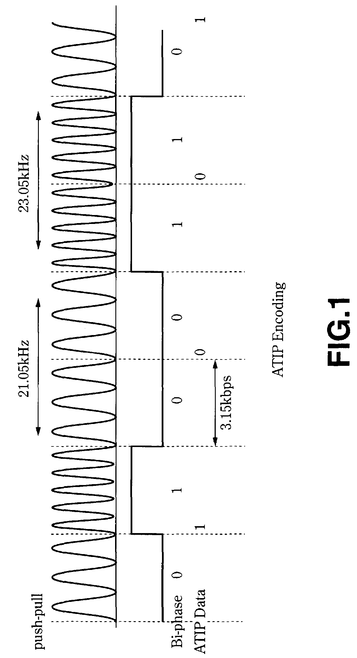
First, in case a groove is wobbled according to FM modulation data as in CD-R and CD-RW, the stroke of a wobble of an adjacent track will cause a phase change of the FM waveform. Thus, in case the track pitch is reduced, an address as ATIP data cannot be reproduced well. In other words, the FM modulation data-based wobbling cannot suitably be used in case the track pitch is narrowed for an improved recording density.
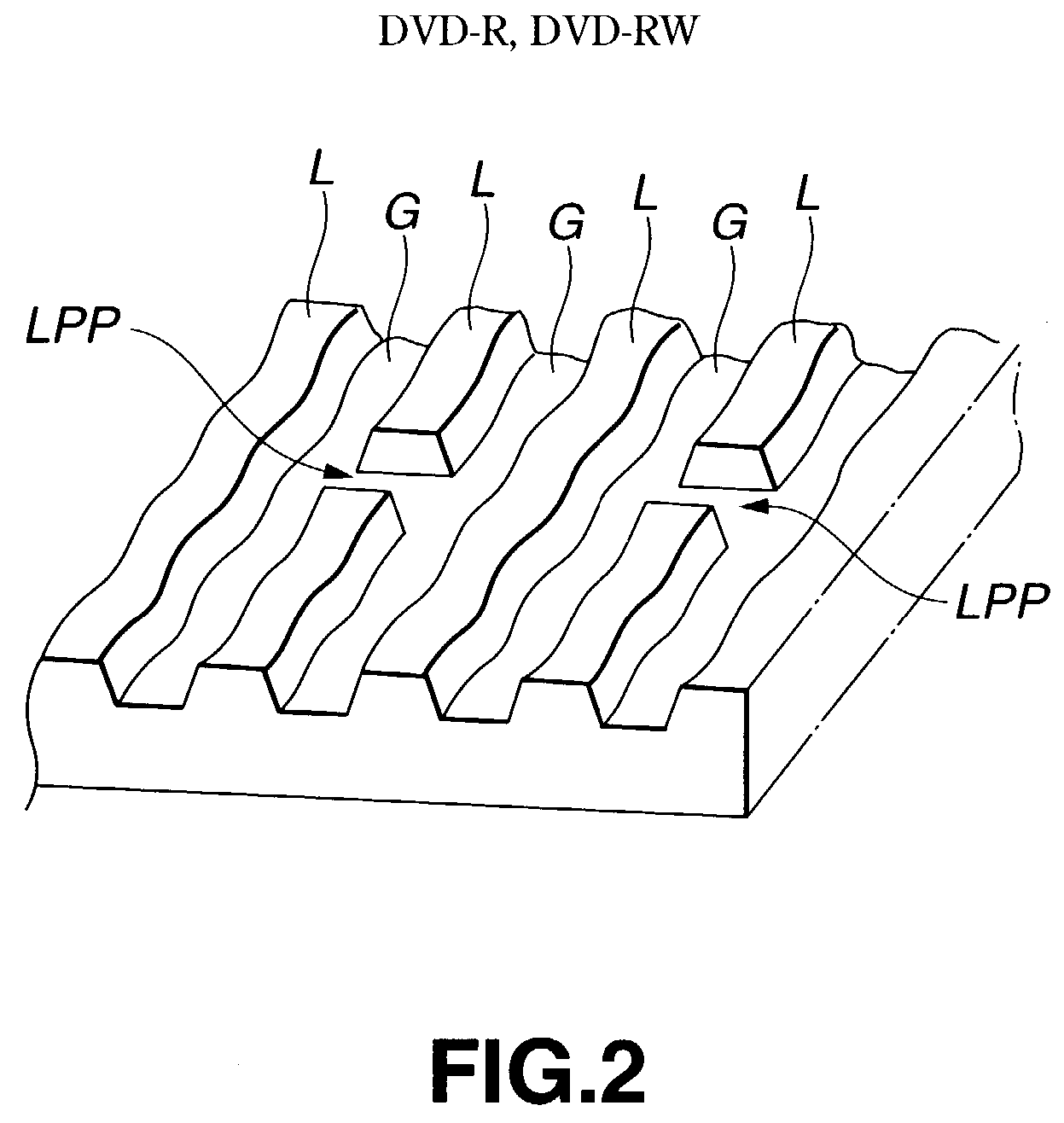
Next, in case land prepits are formed as i

Method used


Image

  • Disc-shaped recording medium, disc-state recording medium cutting apparatus, and disc drive apparatus
  • Disc-shaped recording medium, disc-state recording medium cutting apparatus, and disc drive apparatus
  • Disc-shaped recording medium, disc-state recording medium cutting apparatus, and disc drive apparatus

Examples


Example

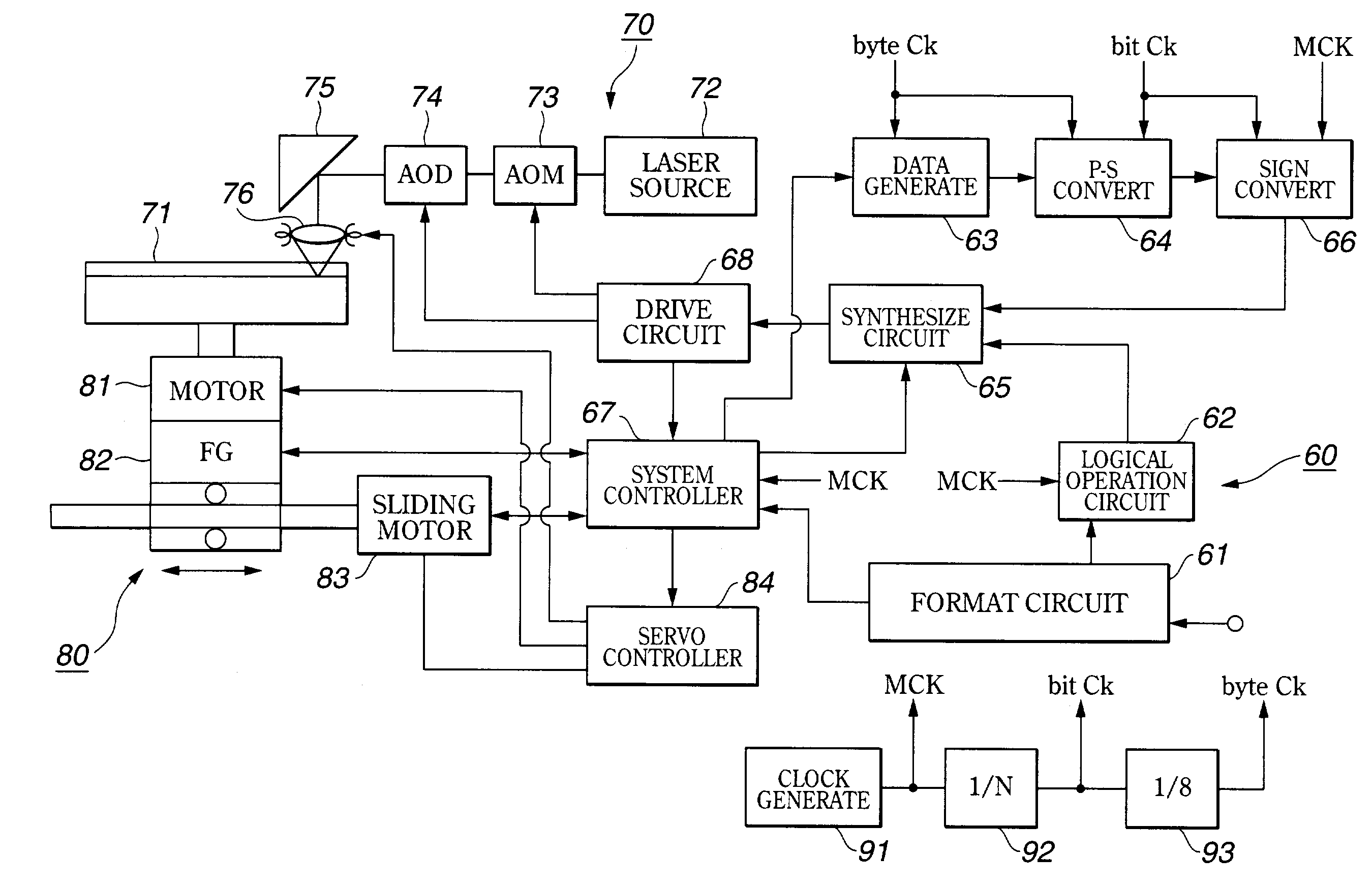
[0080]The description of the present invention will be given in the following order:[0081]First Embodiment:[0082]1-1 Physical characteristics of the optical disc[0083]1-2 Wobbling method[0084]1-3 Cutting apparatus[0085]1-4 Disc drive[0086]Second Embodiment:[0087]2-1 Wobbling method[0088]2-2 Demodulation

[0089]First Embodiment:

[0090]1-1 Physical Characteristics of the Optical Disc

[0091]The physical characteristics of the optical disc according to the present invention and a wobbled track formed on the optical disc will be described below:

[0092]The optical disc according to the present invention is included in the category of discs called “DVR (data and video recording)” for example. It adopts a novel wobbling method dedicated for DVR.

[0093]Table 1 shows the typical parameters of the first embodiment of the optical disc according to the present invention.

[0094]TABLE 1Laser wavelength405nmNumerical aperture (NA)0.85Disc diameter120mmDisc thickness1.2mmDiametrical position of information...

Example

[0210]Second Embodiment:

[0211]2-1 Wobbling Method

[0212]Next, the second embodiment of the present invention will be described. It should be noted that the second embodiment also concerns a disc called “DVR” for example and the physical characteristics of the optical disc are similar to those having previously been described with reference to Table 1 and FIGS. 4A and 4B. The cutting apparatus for use to produce the optical disc and the disc drive for playing the optical disc are also basically similar to those having previously been described concerning the first embodiment. So, the components of the second embodiment, also used in the first embodiment, will not be described any more. Only the wobbling method and associated demodulating method, different from those in the first embodiment, will be described herebelow. In the explanation of the demodulating method, there will also be described an example of the construction of a demodulation circuit used in the disc drive included in ...


PUM


Abstract

There is provided an optical disc having preformed thereon a spiral wobbled track as a grove and/or land along with data is to be recorded. The track is wobbled for a series of predetermined signal units each composed of an FSK information bit part based on a waveform resulted from FSK modulation of information bit and a singe-frequency part based on a waveform of a single frequency. The FSK modulation uses two different frequencies of which the one is the same as the single frequency and the other is different from the single frequency. These different frequencies are in such a relation that each of them has an even number of wobbles and an odd number of wobbles alternately in a predetermined cycle.

Description

TECHNICAL FIELD[0001]The present invention generally relates to a disc-shaped recording medium such as an optical disc, a cutting apparatus for use in production of the disc-shaped recording medium and a disc drive for recording and / or reproducing data to and / or from the disc-shaped recording medium, and more particularly to a disc-shaped recording medium having a wobbled track as a pregroove formed thereon.BACKGROUND ART[0002]To record data to an optical disc which is a disc-shaped recording medium, a guiding means is required for forming a recording track. To this end, pregrooves are preformed on the optical disc and the groove itself or a land, of which the cross section is trapezoidal, between the preformed grooves is used as the recording track.[0003]Address information has to be recorded on an optical disc of this type to permit recording of data in a given position on a recording track on the optical disc. In some cases, such address information is recorded on the optical dis...

Claims


Application Information

Patent Timeline
IPC IPC(8): G11B7/00G11B7/005G11B7/007G11B7/24082G11B7/26G11B20/10G11B20/12G11B20/14G11B27/19G11B27/24G11B27/30
CPCG11B7/0053G11B7/007G11B7/24082G11B7/261G11B20/1217G11B20/1403G11B20/1419G11B27/24G11B7/00718G11B27/3027G11B2020/1222G11B2020/1239G11B2020/1268G11B2020/1269G11B2020/1287G11B2020/1298G11B2220/215G11B2220/216G11B2220/218G11B2220/2537G11B2220/2541G11B2220/2545G11B2220/2562G11B2220/2566G11B2220/257
Inventor IIMURA, SHINICHIROKOBAYASHI, SHOEI
Owner SONY CORP
Why Eureka
Try Eureka