Data replication among storage systems

a data replication and storage system technology, applied in the field of storage systems, can solve the problems of long time spent on the data replication process, the data of the third storage system becomes obsolete, and the time for data reference and data update is extended for normal operation, so as to reduce the storage area of data and achieve high speed

Active Publication Date: 2006-12-19
HITACHI LTD
View PDF78 Cites 35 Cited by
  • Summary
  • Abstract
  • Description
  • Claims
  • Application Information

AI Technical Summary

Benefits of technology

[0009]Another object of the present invention is to enable the reduction of data storage areas provided in a plurality of storage systems. Yet another object is to transfer or replicate data among a plurality of storage systems effectively, at high speed and in a seamless manner, so that the operation of the host computer of the plurality of storage systems is not affected.

Problems solved by technology

Another problem is extending the time for data reference and data update necessary for normal operation.
Furthermore, because a large quantity of the data is the object of replication, a long time is spent on the data replication process and the data of the third storage system becomes obsolete.
As a result, a problem arises when the operation is restarted using the data of the third storage system: a long time is required to update the data of the third storage system and the time to restart the operation is extended.
Therefore, a long time is spent on updating data from the computer, and the time spent on updating data increases with the distance between the first storage system and the second storage system.
As a result, another problem associated with the technology disclosed in the '002 patent is that the distance between the storage systems cannot be increased significantly.

Method used


Image

  • Data replication among storage systems
  • Data replication among storage systems
  • Data replication among storage systems

Examples


first embodiment

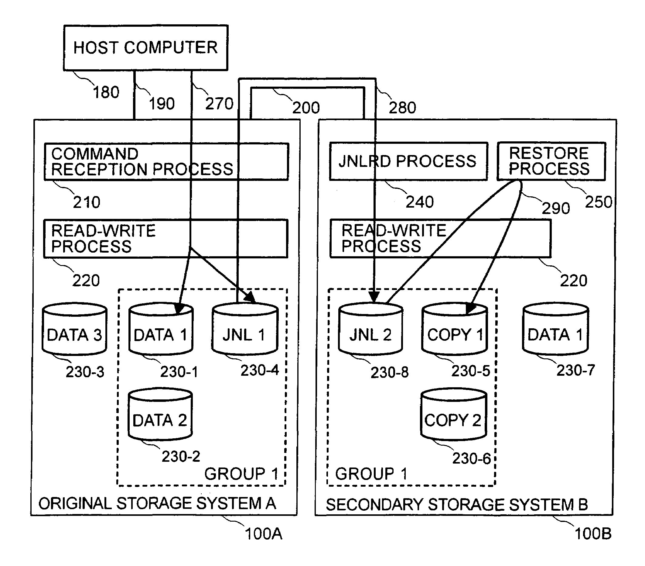
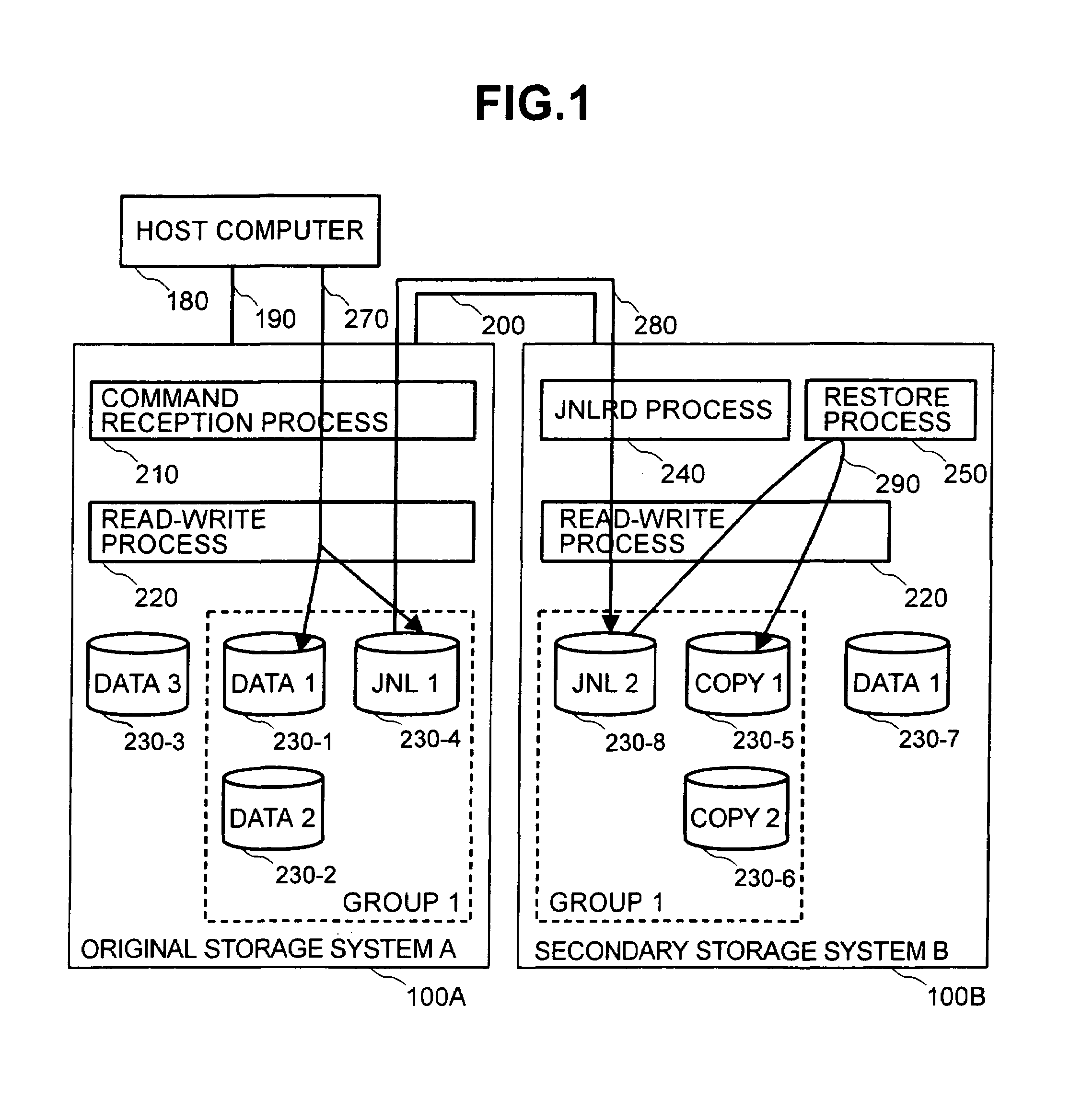
[0034]FIG. 1 is a block diagram illustrating a logical configuration of the present invention.

[0035]In the configuration of the first embodiment of the present invention, a host computer 180 and a first storage system 100A are connected by a connection path 190, and the storage system 100A is connected to a second storage system 100B holding a duplicate of the data retained in the storage system 100A with a connection path 200. In the explanation below, in order to distinguish between the first storage system 100 holding the data which is the object of replication and the second storage system 100 holding the replicated data, we call the storage system 100 holding the data, which is the object of replication, the original storage system 100A, and the storage system 100 holding the replicated data the secondary storage system 1001B. The storage area of the storage system is managed by partitioning and we call the partitioned storage areas logical volumes 230. As shown in FIG. 1, the ...

second embodiment

[0158]FIG. 23 shows a logical configuration of the

[0159]In this configuration, host computer 180 and storage system 100C are connected by connection path 190; storage system 100C and original storage system 100A are connected by connection path 200, and original storage system 100A and secondary storage system 100B are connected by connection path 200. Storage system 100C includes logical volumes 230-9 (ORG1) and 230-10 (ORG2), and conducts the data update of logical volume 230-9 (ORG1) and the data update of logical volume 230-1 (DATA1) in original storage system 100A during the data update into the logical volume 230-9 (ORG1) of storage system 100C.

[0160]Original storage system, 100A, as was described in the first embodiment, conducts the retention of journals in journal logical volume 230-4 (JNL1) using command reception process 210 and read-write process 220 during the data update into the original logical volume 230-1 (DATA1) (2310 in FIG. 23).

[0161]Secondary storage system 100...

third embodiment

[0165]FIG. 24 shows a logical configuration of the

[0166]In this configuration, host computer 180 and storage system 100C are connected by connection path 190; storage system 100C and original storage system 100A are connected by connection path 200, and original storage system 100A and secondary storage system 100B are connected by connection path 200. Storage system 100C conducts data update of a logical volume 230-9 (ORG1) and data update of a logical volume (DATA1) in original storage system 100A during the data update into the logical volume (ORG1) of storage system 100C, as described with reference to the conventional technology.

[0167]Although original storage system 100A is indicated as having the original logical volume (DATA1) to storage system 100C, original storage system does not allocate actual storage areas, that is, storage devices 150. That is, no physical storage areas corresponding to the volume (DATA1) exists in the storage system 10A. For example, it sets numerica...


PUM


Abstract

A first storage system stores information relating to the updating of data stored in that system as a journal. More specifically, the journal is composed of a copy of data that was used for updating and update information such as a write command used during updating. Furthermore, the second storage system acquires the journal via a communication line between the first storage system and the second storage system. The second storage system holds a duplicate of the data held by the first storage system and updates the data corresponding to the data of the first storage system in the data update order of the first storage system by using the journal.

Description

CROSS-REFERENCES TO RELATED APPLICATIONS[0001]The present application claims priority to Japanese Patent Application No. 2003 183734, filed on Jun. 27, 2003.BACKGROUND OF THE INVENTION[0002]The present invention relates to a storage system, and more particularly to data replication among a plurality of storage systems.[0003]A technology relating to data replication among storage systems becomes important for providing uninterrupted service to customers even when failure occurs in a first storage system. The following patent specifications have disclosed a technology for replicating the information stored in a first storage system to a second and third storage system.[0004]U.S. Pat. No. 5,170,480 discloses a technology by which a first computer connected to a first storage system transfers data stored in a first storage system to a second computer via a communication link between a first computer and the second computer, and the second computer transfers the data to a second storage ...

Claims


Application Information

Patent Timeline
Patent Type & Authority Patents(United States)
IPC IPC(8): G06F12/00G06F11/00G06F12/08G06F3/06G06F11/20G06F15/00
CPCG06F11/2064G06F11/2071G06F11/2082G06F17/30312H04L67/1095H04L67/1097Y10S707/99955G06F2201/855G06F16/22
Inventor HIRAKAWA, YUSUKEARAKAWA, HIROSHITAKEDA, TAKAHITOSOTO, TAKAO
Owner HITACHI LTD
Why Eureka
Try Eureka