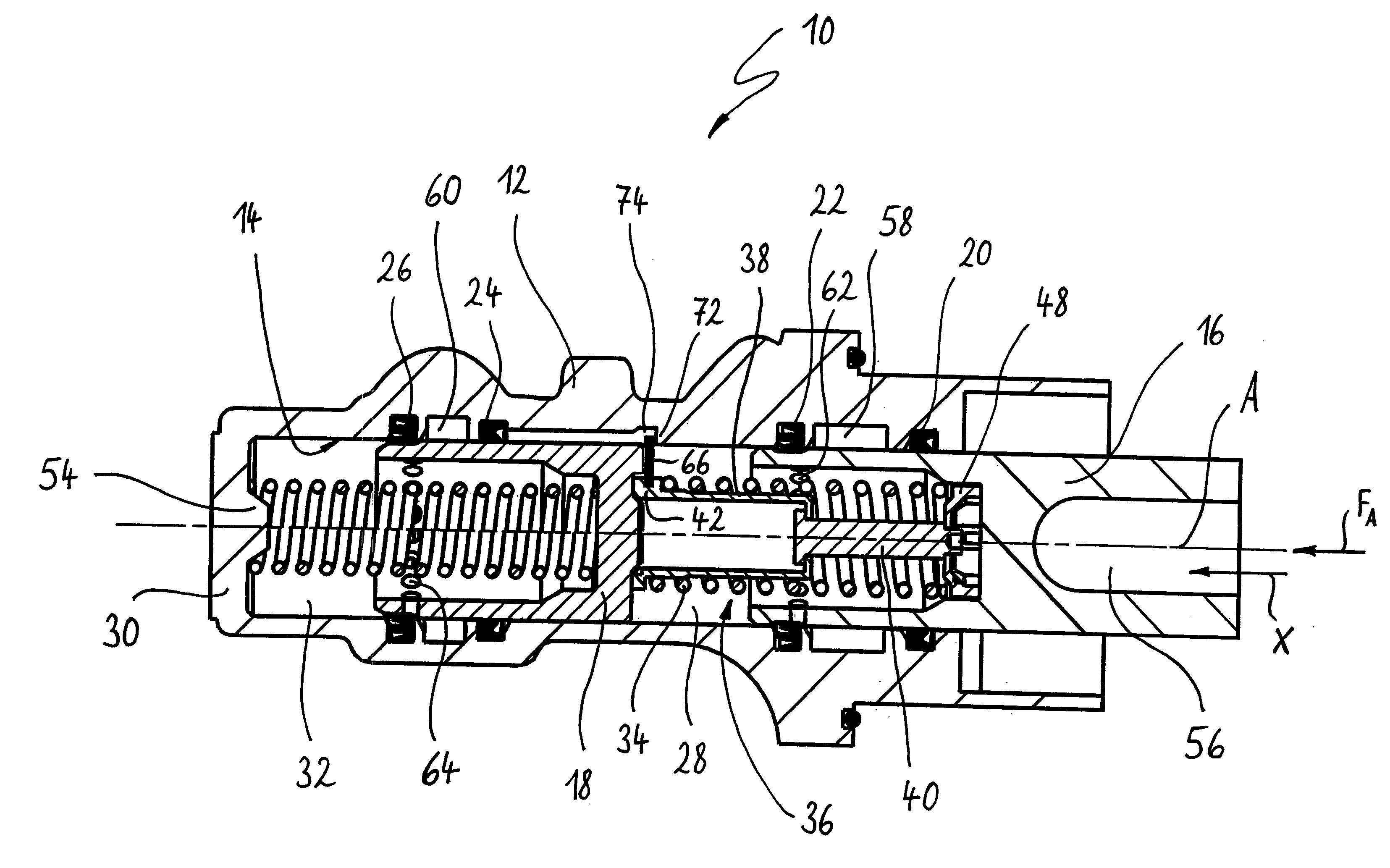
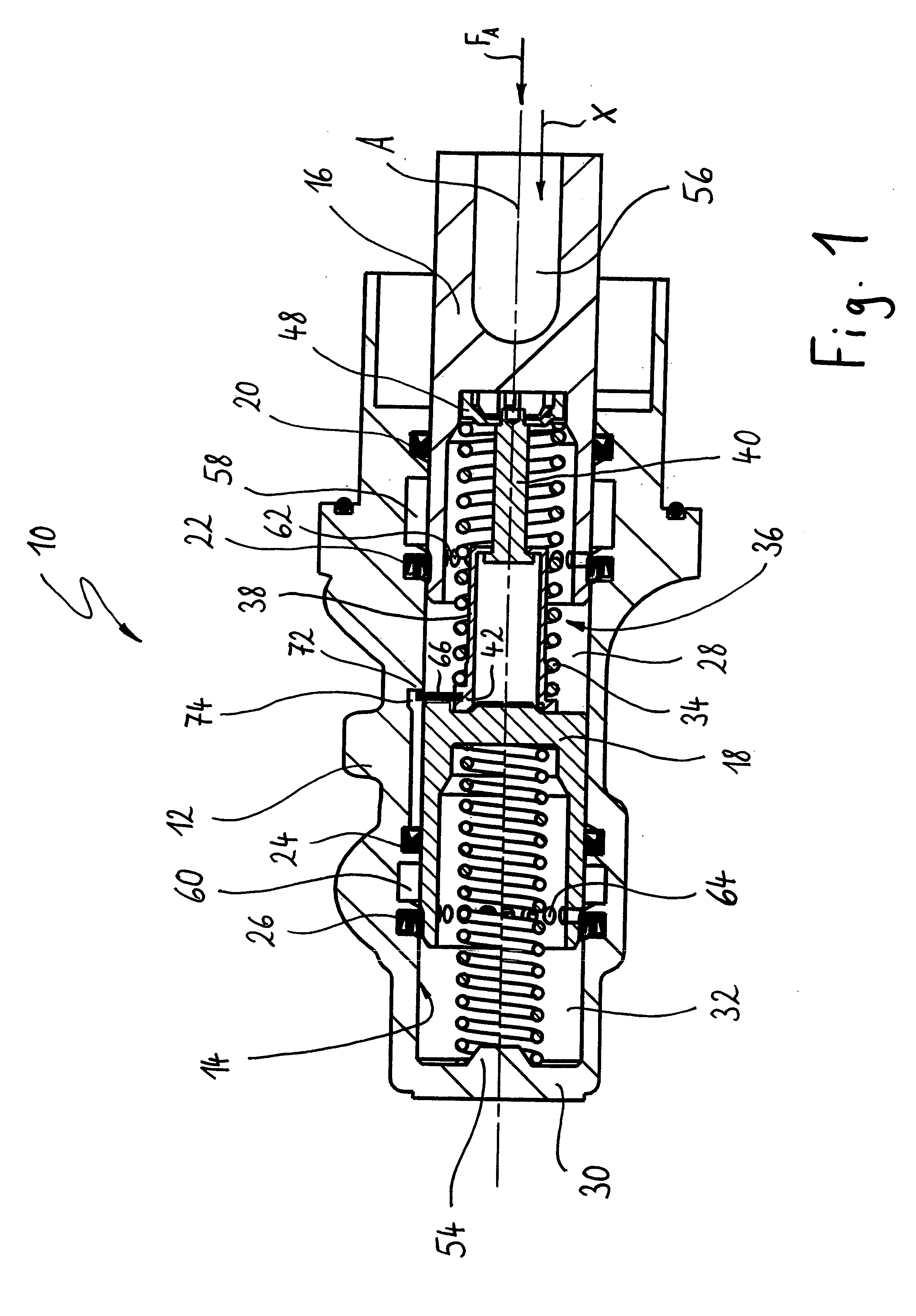
[0008]According to a first form of construction of the present invention, starting with a master cylinder of the initially described construction this object is achieved according to the invention in that—in a transportation or disassembly state of the master cylinder—the second pressure piston is supported by means of a stop component counter to the actuating direction positively in the master cylinder housing. This prevents the second, unrestrained restoring spring from being able to slide the second pressure piston—and hence also the first pressure piston—beyond a constructionally defined extent out of the bore of the master cylinder housing. As the support according to the invention is provided in the master cylinder housing and does not interfere with operation of the master cylinder, there is no need for any kind of removal whatsoever of a transport lock before the master cylinder is installed and / or put into operation.
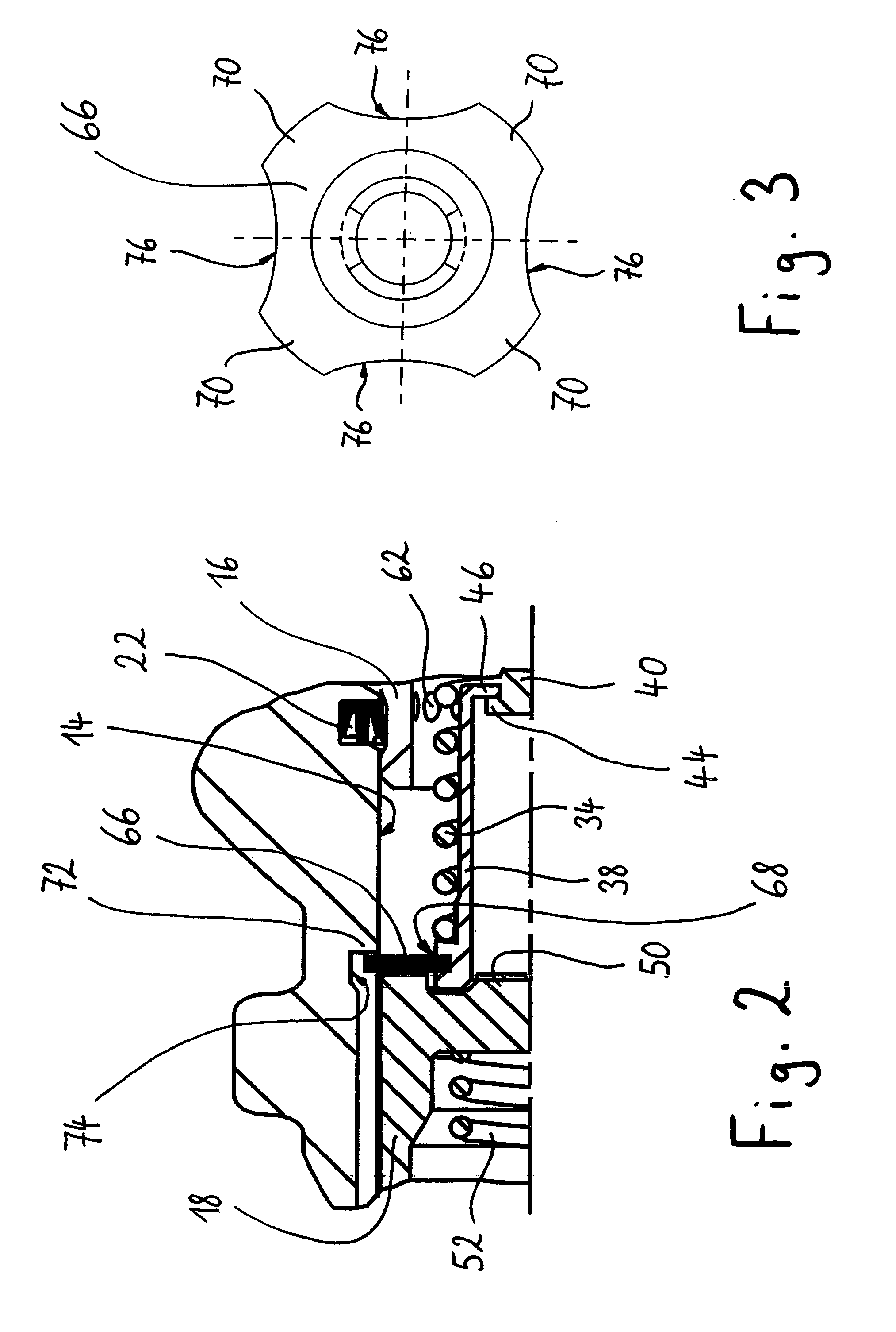
[0011]The stop component is preferably made of elastic material. This enables easy introduction of the stop component into the bore of the master cylinder housing and subsequent latching behind e.g. a stop formed in the bore. According to a particularly preferred construction, such a stop component made of elastic material has a plurality of radial projections, which are arranged distributed in
peripheral direction and which during introduction of the stop component into the bore latch behind a stop in the bore. Situated between the radial projections are fluid-permeable free spaces, so that portions of the bore that are situated in actuating direction behind the stop component may easily be vented.
[0013]In the case of a master cylinder where, for restraining the first restoring spring, i.a. a restraining sleeve having a radially outwardly projecting
flange adjacent to the second pressure piston is used, the stop component is preferably disposed along the restraining sleeve and is pressed by the first restoring spring against the
flange of the restraining sleeve. Such a restraining sleeve may be made of a plastics material or alternatively comprise an e.g. deep-drawn sheet-
metal part. In a modification of this embodiment, between the stop component and the end of the first restoring spring facing the stop component a clamping ring is additionally disposed, against which the first restoring spring is supported. By virtue of the clamping ring, a larger-area and hence more uniform support of the first restoring spring against the stop component is achieved. The material load arising during operation of the master cylinder is therefore advantageously reduced.
[0015]According to a second form of construction of the present invention, starting with a master cylinder of the initially described construction the initially stated object is achieved according to the invention in that, for restraining the second restoring spring, each end thereof is supported against a tensioning plate, wherein the two tensioning plates are connected to one another in a tension-resistant manner by means of a cable, which extends through the second restoring spring. Such a restraint of the second restoring spring saves weight and is particularly economical to manufacture. For fastening the cable to the tensioning plates, each tensioning plate preferably has a recess, which tapers in the direction of the second restoring spring and through which the cable runs and into which fits a clamping element that is fastened, e.g. by crimping, on the respective end of the cable. In a constructionally advantageous variant of this form of construction, each tensioning plate has a radial slot, which extends from the recess to the outer edge of the tensioning plate and allows throughfeed of the cable. Given such a form of construction, therefore, the clamping elements may first be fastened to the cable and then the cable provided with the clamping elements may be inserted into the tensioning plates. Instead of using clamping elements, it is possible for the cable to be soldered or glued to each tensioning plate in order to fasten the cable to the tensioning plate.
[0016]According to a third form of construction of the present invention, starting with a master cylinder of the initially described construction the initially stated object is achieved according to the invention in that the first pressure piston protrudes from the bore and that the end of the first pressure piston protruding from the bore is supported counter to the actuating direction against rolled
bellows, which are fastened to the housing of the master cylinder. In said case, the rolled
bellows are preferably fixed in a
peripheral groove in the outside of the housing close to the open end of the bore. The rolled
bellows moreover preferably encompass the end of the first pressure piston protruding from the bore in that the rolled bellows overlap an end face disposed on the protruding end of the first pressure piston in order in this way to prevent the first pressure piston from falling out of the bore.



