Thermal energy transfer unit and method

a technology of thermal energy transfer and energy storage system, which is applied in the field of thermal energy transfer system, can solve the problems of cumbersome solution to the problem of freon management in the storage system of ice on the pipe, increasing the importance of freon management, and eliminating the possibility of multiple air conditioning systems

Inactive Publication Date: 2006-12-26
HALL THERMAL
View PDF18 Cites 34 Cited by
  • Summary
  • Abstract
  • Description
  • Claims
  • Application Information

AI Technical Summary

Benefits of technology

[0018]It is therefore one object of this invention to provide a thermal energy transfer unit which can be retrofitted to an existing Freon air conditioning system without the requirement that the storage tank be located in close proximity to the condensing unit.

Problems solved by technology

When using Freon for “ice on pipe” thermal energy conversion and storage, the problem of Freon management becomes increasingly important.
The solution to the problem of Freon management in “ice on pipe” storage systems has been cumbersome with a number of different solutions having been proposed over the years.
These solutions are complicated and eliminate the possibility of multiple air conditioning systems using a common storage tank.
It is more expensive to provide multiple thermal energy tanks than to provide one tank of the combined volume.
These solutions also eliminate any advantage which other thermal energy storage methods might offer.
The additional cost and inconvenience of the copper tubing connecting the coil and the compressor must be taken into consideration when the two are located apart at a relatively great distance.

Method used


Image

  • Thermal energy transfer unit and method
  • Thermal energy transfer unit and method
  • Thermal energy transfer unit and method

Examples


Embodiment Construction

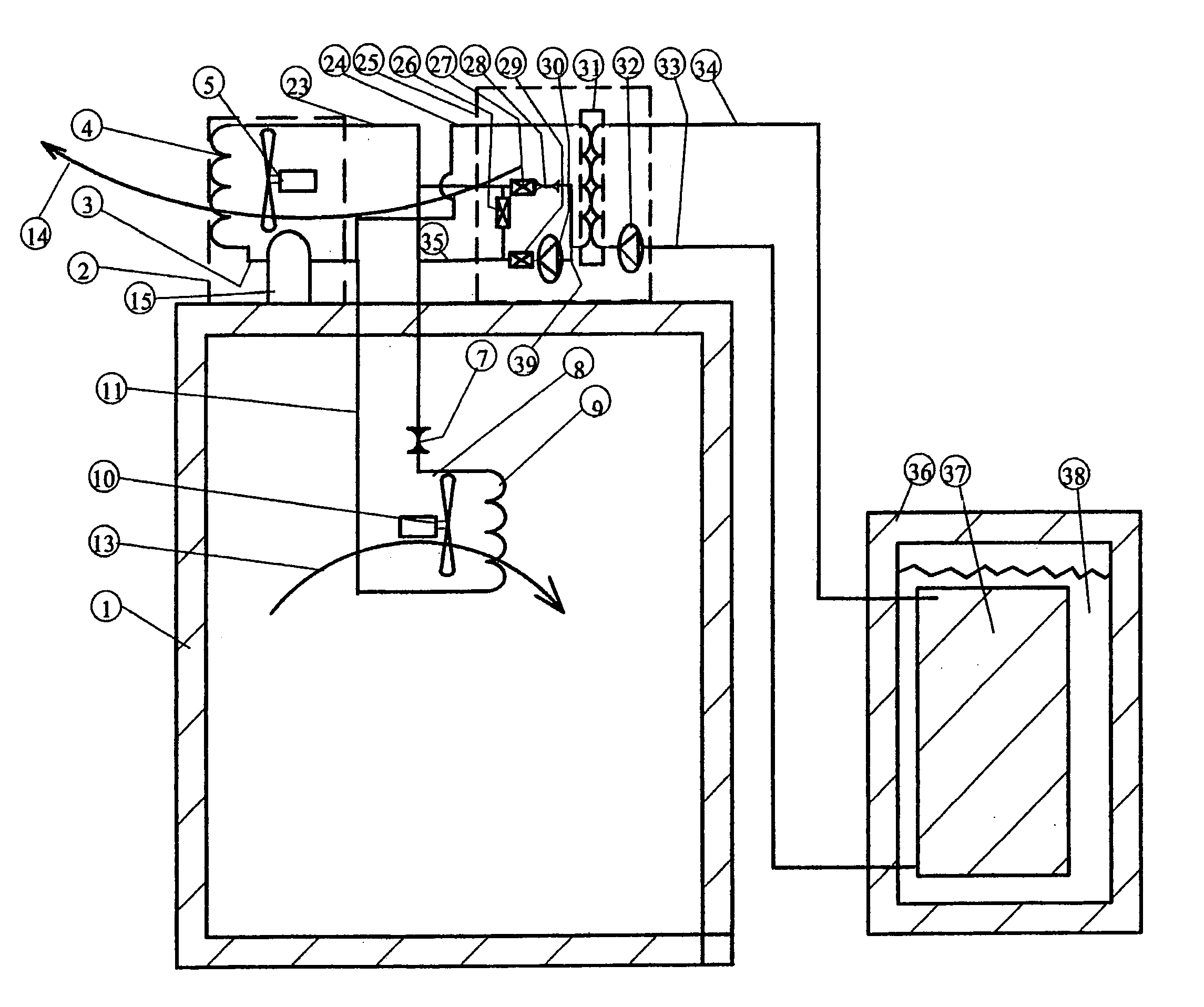
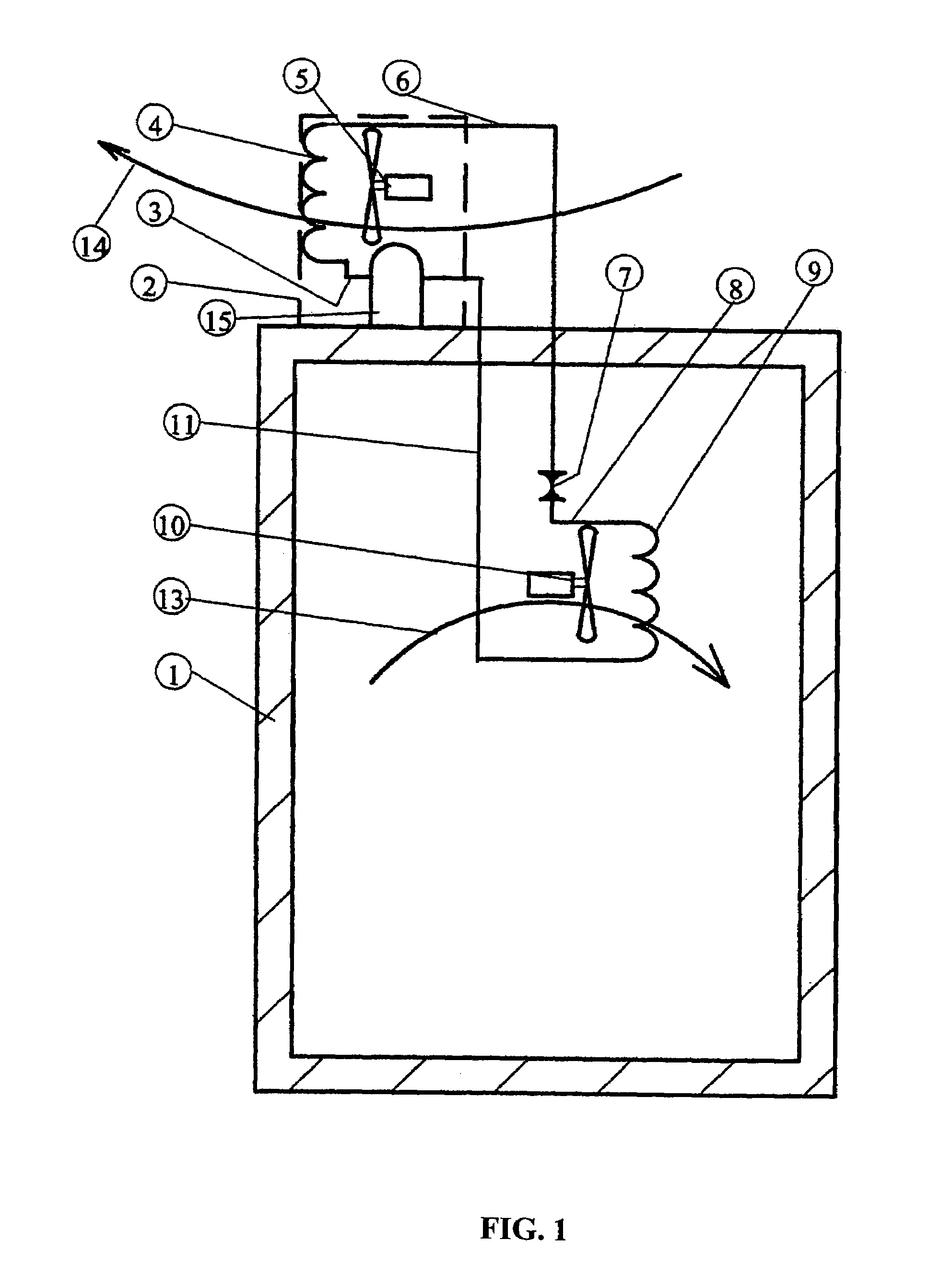
[0034]FIG. 1 shows a conventional Freon air conditioning system on a building (1) to be cooled. In the discussion which follows, the term “Freon air conditioning” is intended to describe any conventional mechanical compression refrigeration or air conditioning system using a compressible refrigerant and an expansion device in a closed circuit to achieve a cooling effect. It will be understood that other refrigerants besides “Freon” will be known to those skilled in the relevant industries. The building has an evaporator coil (9), an expansion device (7), and a motorized air mover (10) located inside the building. The air inside the building (13) is moved past the evaporator coil when the motorized air mover (10) is running. Outside the structure (1) a conventional condensing unit (2) is shown. The condensing unit consists of a compressor (15), a condensing coil (4), and a motorized air moving unit (5). Outside air (14) is moved past the condensing coil (4) when the motorized air han...


PUM


Abstract

A thermal energy transfer unit is provided for conventional Freon air conditioning. One or several thermal energy transfer units are operatively interconnected to one or several conventional air condition systems and share a common energy storage tank. Each thermal energy transfer unit converts energy from the compressor and condensing coil of the conventional air conditioner and stores it in the common energy storage tank when electricity is in low demand. Each thermal energy transfer unit retrieves stored energy from the common storage tank and provides air conditioning without the use of the compressor when electricity is in high demand. Each thermal energy transfer unit can be disabled to allow the air conditioning unit to perform as if they and the energy storage tank were not connected. One or all of the units can be disabled without affecting the performance or purpose of the others.

Description

BACKGROUND OF THE INVENTION[0001]1. Field of the Invention[0002]The present invention relates generally to a thermal energy transfer system for cooling a structure which can easily be added to an existing Freon compression air conditioning system which will replicate the operation of a conventional condensing unit while using only energy which was previously stored in the system and which does not require modification of the components of the air conditioning system normally located within the structure being cooled.[0003]2. Description of the Prior Art[0004]Because the utility electrical industry has incorporated reduced electrical rates in off-peak hours when demand is low, the electrical consumer has found it advantageous to purchase and store air conditioning in the off-peak hours and use it during peak hours. There are many methods of storing and retrieving thermal energy in an insulated tank. All require an insulated tank that contains a substance in which the thermal energy i...

Claims


Application Information

Patent Timeline
Patent Type & Authority Patents(United States)
IPC IPC(8): F25D17/02A45C11/24A63B55/00
CPCF24F5/0017F25D17/02F28D20/0034F28D20/021F25B2400/24Y02E60/142Y02E60/145Y02E60/147F24D17/02Y02E60/14A63B55/40
Inventor ANDERSON, R. DAVID
Owner HALL THERMAL
Why Eureka
Try Eureka