Methods and apparatus for rapidly measuring pressure in earth formations

Inactive Publication Date: 2006-12-26
SCHLUMBERGER TECH CORP
View PDF38 Cites 48 Cited by
  • Summary
  • Abstract
  • Description
  • Claims
  • Application Information

AI Technical Summary

Benefits of technology

[0009]It is therefore an object of the invention to provide method

Problems solved by technology

It has been discovered that one of the reasons why the existing MDT tool and tools like it are slow to measure pressure is because they have voluminous flow lines with dead ends that are liable to trap ot

Method used


Image

  • Methods and apparatus for rapidly measuring pressure in earth formations
  • Methods and apparatus for rapidly measuring pressure in earth formations
  • Methods and apparatus for rapidly measuring pressure in earth formations

Examples


Example

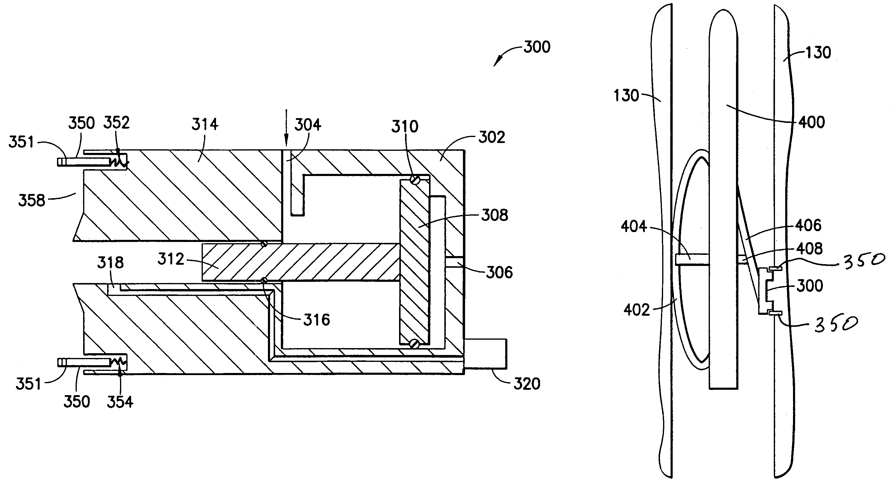
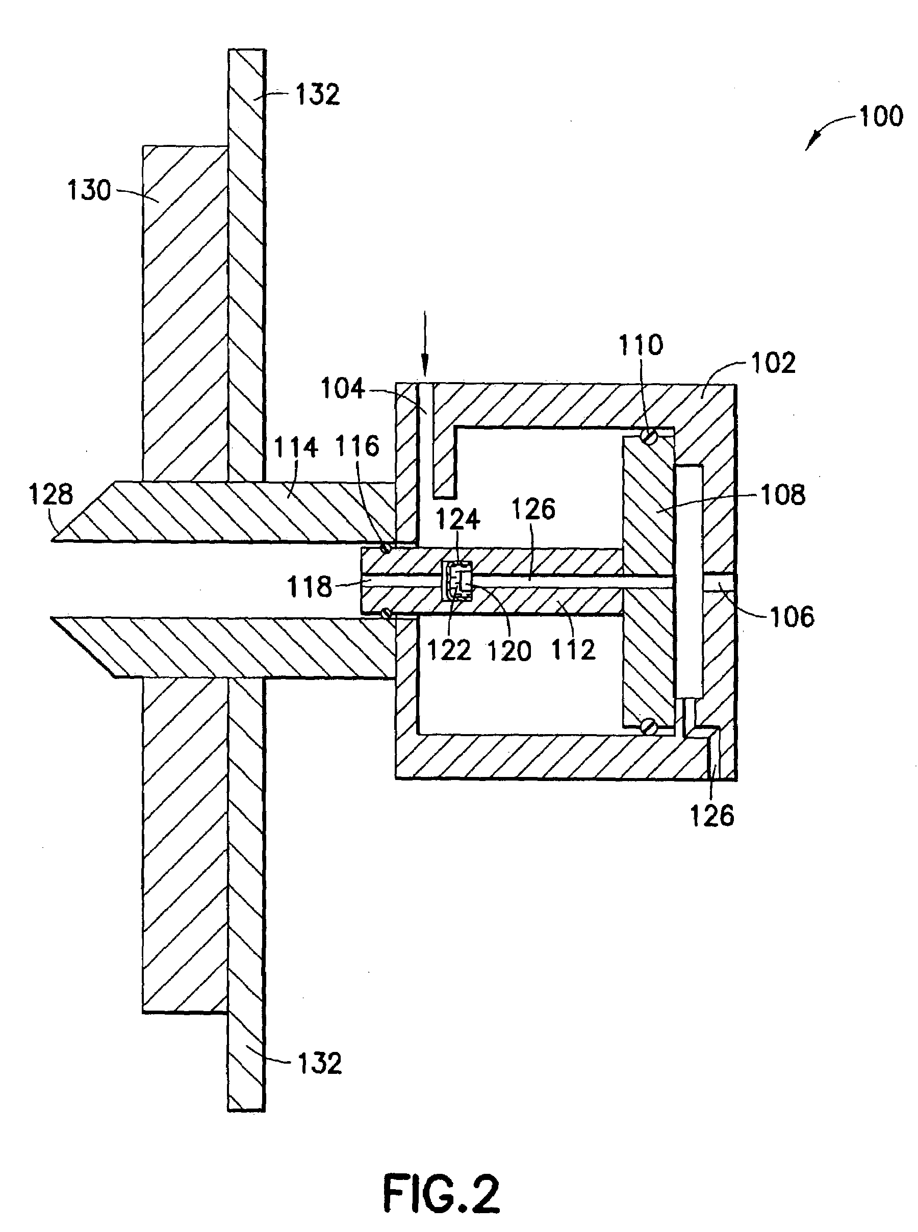
[0023]Referring now to FIG. 2, the probe 100 includes an hydraulic cylinder 102 having a first fluid inlet 104 and a second fluid inlet 106 with a first piston 108 disposed therebetween. The fluid on either side of the piston 108 is sealed by an O-ring 110. A second piston 112, which is attached to or integral with the first piston 108, extends from the first piston 108 into a fluid cylinder 114 (attached to or integral with the hydraulic cylinder 102) and is sealed with an O-ring 116. The second piston 112 has a bore 118 which extends into a chamber within the piston containing a pressure sensor 120, covered with a fluid 122 and a diaphragm 124. An electrical cable connection 126 extends from the pressure sensor 120 through the pistons 112, 108 and out through the cylinder 102. The fluid cylinder 114 has a tapered end 128 for insertion into the formation. A packer 130 (illustrated schematically) is preferably mounted adjacent the cylinder 114 for moving the cylinder into and out of...


PUM


Abstract

Methods and apparatus for rapidly measuring pressure in earth formations are disclosed. According to a first embodiment of the apparatus, a probe is provided with a movable piston having a sensor built into the piston. According to a second embodiment of the apparatus, the pressure sensor is mounted adjacent to or within the piston cylinder and a fluid pathway is provided from the sensor to the interior of the cylinder. Methods of operating the first and second embodiments include delivering the probe to a desired location in a borehole, setting the probe against the formation, and withdrawing the piston to draw down fluid for pressure sensing. A third embodiment of the probe is similar to the second but is provided with a spring loaded metal protector surrounding the cylinder and an annular rubber facing. The third embodiment is preferably used in a semi-continuous pressure measuring tool or an LWD tool having a piston controlled bowspring and a piston controlled articulated member carrying the probe. The tool is moved in a semi-set mode and when located at a desired depth is rapidly put in a fully-set mode.

Description

[0001]This application is a continuation-in-part of U.S. patent application Ser. No. 10 / 285,788, filed Nov. 1, 2002, now abandoned assigned to the same assignee as the present application.[0002]This application is related to co-owned U.S. Pat. Nos. 4,936,139 and 4,860,581, the complete disclosures of which are hereby incorporated by reference herein.BACKGROUND OF THE INVENTION[0003]1. Field of the Invention[0004]The invention relates to the production of hydrocarbons from an underground formation. More particularly, the invention relates to testing earth formations to determine formation pressure.[0005]2. State of the Art[0006]The previously incorporated co-owned U.S. Patents describe technology used in the assignee's commercially successful borehole tool, the MDT (a trademark of Schlumberger). The MDT tool is a wireline tool which includes a packer and a probe which enable the sampling of formation fluids and the measuring of pressure transients during sampling or a pretest. One ca...

Claims


Application Information

Patent Timeline
IPC IPC(8): E21B47/06E21B49/10E21B49/00
CPCE21B47/06E21B49/008E21B49/10
Inventor RAMAKRISHNAN, TERIZHANDUR S.DONZIER, ERIC
Owner SCHLUMBERGER TECH CORP
Why Eureka
Try Eureka